Exploring How Injection Molded Magnets Are Created


You make injection molded magnets by mixing magnetic powder with a polymer binder. Most companies use a mix from 85:15 to 95:5 by weight. This mix gives strong magnet power and good strength. You get the materials ready, mix them, and put them in molds. You can make magnets in many shapes and sizes. You get a product that fits special needs and has exact properties.

  • Typical composition ratios:

    • 85:15 magnetic powder to polymer binder

    • 95:5 magnetic powder to polymer binder


What Are Injection Molded Magnets

Key Characteristics

Injection molded magnets are special because of how they are made. You mix magnetic powder with a thermoplastic resin. Then you put the mixture into a mold to shape it. This way, you can make magnets with tricky shapes and exact sizes. These magnets are different from other types. Look at the table below to see the differences:

Feature

Injection Molded Magnets

Other Types of Magnets

Manufacturing Process

Mixed thermoplastic resin with magnetic powders

Varies (e.g., sintering, bonding)

Shape Complexity

High precision, complex shapes possible

Limited shape options

Polymer Binder Content

Higher content for better corrosion resistance

Varies, often lower

Surface Coating Requirement

Generally not needed

Often required for protection

Mechanical Strength

High

Varies


Injection molded magnets have many good physical and magnetic features:

  • They can be made with very exact sizes, even up to 0.01mm.

  • They are strong and do not break or twist easily.

  • They last longer in tough places because they resist chemicals.

  • You can pick neodymium or hard ferrite materials.

  • Neodymium magnets do not need extra coatings since they protect themselves.

  • You can make any shape and choose how the magnet works, like isotropic injection molded neodymium magnets.

  • These magnets work well, are light, and look smooth.

Tip: You can use injection molded magnets when you need to make a lot of parts. You can also put them right onto other pieces.


Common Uses

Many industries use high temperature resistant injection molded magnets because they are flexible and dependable. Here are some ways they are used:

Industry/Application

Description

Magnetic Sensors

Used for detecting magnetic fields in various devices.

Magnetic Brakes

Employed in systems requiring controlled braking mechanisms.

High Volume Production

Ideal for creating numerous identical components quickly and efficiently.


You will see these magnets in tiny motors, machines that work by themselves, and electronic gadgets. They work well and can be made in many shapes, so they are great for new technology. You can trust them to stay strong during earthquakes and to work the same way every time, even in tough places.


Materials for Injection Molded Magnets

Magnetic Powders

You must pick the right magnetic powder. The powder you choose affects how strong your magnet is. It also changes how the magnet works in different places. Here are the main powders you can use:

  • Ferrite

  • NdFeB (Neodymium Iron Boron)

  • SmCo (Samarium Cobalt)

Each powder is good for different things. Ferrite is cheap and works for simple jobs. NdFeB makes very strong magnets for tough tasks. SmCo is best when you need magnets that work in high heat.

How much magnetic powder you use matters. If you use less powder, the magnet is not as strong but it is tougher. If you use more powder, the magnet does not get much stronger and can break more easily.


Polymer Binders and Additives

You mix the magnetic powder with a polymer binder. The binder keeps everything together. It helps you shape the magnet and makes it last longer. Solid epoxy resin is used a lot because it is easy to mold. But epoxy does not work well in high heat or with chemicals. Polyamide 12 (PA12) lets you add more powder, so the magnet works better. Polyphenylene sulfide is good for hot places, but you cannot add much powder. Polyether Ether Ketone is great for very high heat and meets tough aerospace rules.

Additives help with mixing and molding. First, you blend the powder and binder to get the right flow. This careful mixing helps you make magnets with the shape and strength you want.


Manufacturing Process
Making injection molded magnets has many steps. You must follow each step closely. This helps the magnets have the right shape and strength. It also makes sure they work well. This process lets you make lots of magnets at once. You can also make magnets with tricky shapes.


Mixing and Granulation

First, you mix magnetic powder with a thermoplastic binder. Mixing is important because it makes the blend even. If you do not mix well, the magnets will not work right. Special machines help with mixing. Here is a table with common machines:

Equipment Type

Description

Internal mixers

Used for thorough mixing of materials

Dual planetary mixers

Provides efficient mixing and kneading

Dual eccentric wheel mixers

Offers unique mixing capabilities

Single screw extruders

Commonly used for material extrusion

Z-type gear mixers

Ensures uniform mixing of components


After mixing, you break the blend into small pieces. These pieces are called granules. Granules move easily into the mold.

Tip: Good mixing and granulation stop weak spots from forming in your magnets.


Mold Design

Mold design decides the magnet’s shape and how it works. You need to focus on this step. Here are some things to remember:

  • Careful cutting of mold spaces helps you get exact sizes.

  • Good mold design spreads the material evenly. This makes magnets stronger and lowers defects.

  • You can set the magnet’s direction during or after molding.

A smart mold design lets you make magnets with special shapes and sizes. You can also make sure every magnet fits your needs.


Injection Molding Steps

Next, you heat the granules until they melt. Then you push the melted mix into the mold. The mold gives the magnet its final look. You can use two molds for harder designs or extra features.

Temperature and pressure are very important here. Here are some key points:

  • More pressure helps fill thin or long molds faster. It also cools the magnets quicker.

  • The polymer melt must stay hot enough. This helps make thin parts.

  • Rapid Temperature Cycling (RTC) can heat the mold fast. Sometimes it heats up by 200 °C in seconds. This makes the process quicker.

You can make many magnets at the same time. This is good for making lots of magnets.


Cooling and Demolding

After molding, you cool the magnets down. Cooling keeps their shape and strength. You must watch the temperature to stop problems. Here is a table with things to manage:

Aspect

Description

Temperature Control

Strict control of barrel and mold temperatures to prevent defects.

Mold Design Optimization

Ensuring uniform and effective cooling systems to avoid temperature gradients during cooling.

Injection Process Control

Controlling parameters like pressure, speed, and time to ensure even cooling and reduce internal stress.


When the magnets are cool, you take them out of the mold. This is called demolding. If you do this too early or late, the magnets might crack or bend.


Quality Control

You want every magnet to be good. Quality checks help you find problems early. Here is a table with main checks:

Quality Control Measure

Description

Material Testing

Tests the composite material for magnetic properties, flow characteristics, and thermal stability.

Dimensional Inspection

Inspects finished magnets for dimensional accuracy, including size, shape, and surface finish.

Magnetic Performance Testing

Assesses the magnet's strength and properties, including magnetic field strength and coercivity.

Endurance Testing

Conducts tests to evaluate long-term performance under simulated operating conditions.


You may face some problems while making magnets. High costs, strict rules, and supply issues can slow you down. Some places do not know much about injection molded magnets. This can make starting hard.

Note: Making injection molded magnets can affect the environment. You should think about energy use, safe materials, and recycling. Many companies now use green methods to help the planet.

Every step in making magnets is important. Careful planning helps you make strong magnets for many jobs.


Custom Injection Molded Magnets

Design Flexibility

You can make custom complex shape injection molded permanent magnets. This helps you match the magnet to your product’s needs. You might want a ring or a tricky 3D shape. Both are possible with this method. The table below lists some ways to customize magnets:

Customization Method

Description

Insert Molding

The magnet goes in the mold. Plastic flows around it.

Over-Molding

The magnet is covered in plastic. This is good for tough places or medical use.

Ultrasonic Welding

Two pieces with magnets join together. They fuse using fast vibration.

Snap On

Two plastic parts snap together. This holds the magnet in place.

Screw/Bolt

The magnet has a spot for screws. You can secure it easily.

Melt Rivet

A plastic stud melts into a hole in the magnet.


You can ask for any shape or size you want. If you do not have a drawing, the maker can help you design one. They can also give you samples to test. This freedom lets you make products that work better and look nicer.

Tip: Custom injection molded magnets let you mix features in one part. This makes designing easier.


Production Scale and Efficiency

You can make lots of custom high tolerance injection molded magnets at once. The process works for small or big orders. Every magnet looks and works the same. This helps your devices work better. You save time and money because the process is quick and uses less material. Many companies pick this way when they need many strong magnets.


Enhanced Properties with Additives

You can add special materials to make magnets work better. For example, mixing 65% isotropic NdFeB powder with 35% polyamide (Nylon-12) makes strong magnets. These extras help you get the right mix of strength and flexibility. You can also make magnets that handle heat or tough places. Additives and smart mold design help you make magnets for special jobs, like medical tools or electric motors. This helps you get the best results for your needs.


Advantages of Injection Molded Magnets

Precision and Complexity

Injection molded magnets can be made very exact. You can create shapes with lots of detail. These magnets fit into devices without problems. The process repeats the same shape every time. This means you do not get mistakes. Check the table to see how these magnets compare to older ways:

Feature

Injection Molded Magnets

Traditional Methods

Design Flexibility

High

Limited

Precision

High

Variable

Magnetic Strength

Moderate

High

Temperature Stability

Moderate

High


Tip: You can make special shapes for electronics and medical tools.


Cost-Effectiveness

Using injection molded magnets helps you spend less money. Making them uses less energy. There is not much waste. You can use recycled stuff in the binder. This helps the planet. Here are some reasons why this way saves money:

  • Uses less energy

  • Makes less waste

  • Can use recycled materials

  • Mixes magnet and plastic molding together


See the table to compare with other magnets:

Advantage

Injection Molded Magnets

Sintered Magnets

Bonded Magnets

Cost-Effectiveness

Yes

No

Yes

Design Complexity

High

Low

Medium

Energy Efficiency

High

Low

Medium

Environmental Impact

Low

High

Medium

Note: You can mold magnets onto other parts. This saves time and makes building easier.


Versatility

Injection molded magnets work in many places. You can pick from lots of materials. Some choices are ferrite, neodymium, and samarium cobalt. You can also choose polymers like nylon or PPS. This helps you match the magnet to your job. Here are some ways people use these magnets:

  1. Cars: Sensors, motors, and actuators

  2. Electronics: Speakers, sensors, and tiny motors

  3. Medical: MRI machines and surgery tools

  4. Factories: Magnetic pumps and couplings

  5. Planes: Navigation and control systems

You can make magnets that are light and strong. They do not rust and work in hard places. This makes it easy to find the right magnet for your project.


You make injection molded magnets by mixing magnetic powder and a polymer binder. Then you put the mix into molds to shape them. After that, you cool the magnets so they become strong. This way, you can make magnets in many shapes and sizes.

  • These magnets do not rust easily and are always the same.

  • You spend less money because there is little waste and the process is quick.

  • You can design magnets for special uses, even if you need exact sizes.
    If you want magnets that are both exact and flexible, this method is a good choice.
What are the requirements for the positioning of the impeller of the multi-stage mid-open pump?

What are the requirements for the positioning of the impeller of the multi-stage mid-open pump?


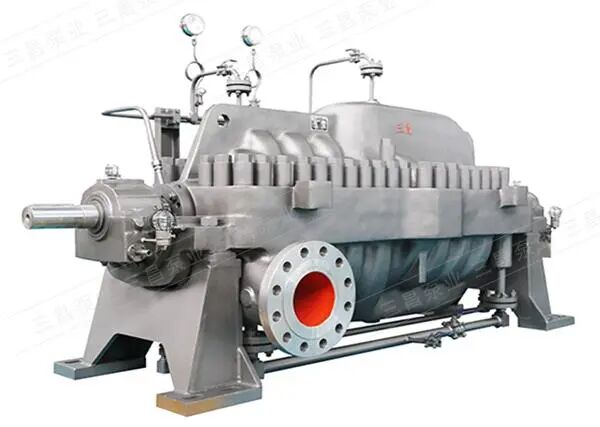
The impeller positioning of multi-stage horizontal split pump is the core key step in the assembly process, which is directly related to the running efficiency, vibration noise and service life of the pump. The core goal of the positioning is to ensure that the exit center of all impellers is in a straight line and the inlet center of the guide vane is aligned.

The following are the detailed multi-stage middle open pump impeller positioning method, steps and matters needing attention.


1、 Core Principle


The position of each impeller in the multi-stage pump is not fixed by the axial distance of the bushing, but by the axial total displacement of the rotor.

The total axial displacement of rotor components refers to the axial movement distance of the entire rotor (including the shaft, all impellers, balance disc, etc.) from one extreme position to the other extreme position without installing thrust bearings.

The purpose of positioning is to ensure that the axial thrust caused by temperature rise and pressure during pump operation will not cause friction between the impeller and stationary components (such as pump casing and inlet ring). It also ensures the alignment of the impeller outlet with the guide vane inlet at each stage to achieve better hydraulic performance.


2、 Location methods and procedures


The "rotor trial fitting method" or "measurement and calculation method" is commonly used, both of which are fundamentally similar. Below are the detailed steps combining both methods:


Step 1: Preparation and Initial Assembly

Cleaning and Inspection: Thoroughly clean all pump components including the shaft, impellers, bushings, and balance discs, ensuring no burrs or damage.

Measure the impeller width and sleeve length separately (if applicable) and record the data. This will facilitate cross-validation in subsequent steps.

Initial assembly: Install the first-stage impeller, subsequent impellers, shaft sleeves, and balance discs sequentially onto the pump shaft. Do not tighten the fixing nuts (e.g., balance disc nuts) initially, allowing all components to maintain axial sliding relative to the shaft.


Step 2: Measure the total rotor clearance

The assembled rotor (without bearings) is hoisted into the lower half of the pump housing.

A dial gauge is installed at one end of the pump shaft (usually the drive end), with its head pointing toward the shaft's end face, to measure axial displacement.

Manually push the entire rotor toward the pump's drive end (DE) until it can no longer be moved (e.g., when the first-stage impeller contacts the pump body). Then, reset the dial gauge to zero.

Manually pull the entire rotor toward the non-driving end (NDE) of the pump until it can no longer be moved (e.g., when the final-stage impeller or balance disc contacts the pump body). The dial gauge reading at this point is the 'total rotor runout.' Record this value as S_total.

To ensure accuracy, perform multiple push-pull cycles and verify the stability of the dial gauge reading.


Step 3: Align the impeller position

After the total run-off is measured, the ideal working position of the impeller should be in the middle of the total run-off.

Calculate the center position: Push the rotor to the midpoint of the total stroke. For example, if the total stroke S_total is 4.0 mm, the center position is 2.0 mm from the driving end's limit position to the non-driving end.


Verify alignment (core check):

Method A (traditional method): Using a feeler gauge or long feeler gauge, measure the gaps between the center of each impeller outlet and the corresponding guide vane inlet center in all directions. Under ideal alignment, these gaps should be essentially equal. If the gap deviation of any stage is excessive, it indicates that the axial position of that impeller stage is incorrect.

Method B (marking method): On the middle plane of the pump body, mark the center of each guide vane inlet with red lead or marker pen. Then rotate the rotor to check if the outlet edges of each impeller align with these marks. This is the most intuitive and effective method.

Adjustment: If misalignment is detected, it may require fine-tuning the bushing length or inserting shims between the impeller hubs. For mature designs, this step is usually unnecessary, as proper total runout ensures natural alignment.


Step 4: Fix the rotor and set the working stroke

After the center position is determined, the rotor component must be locked in this relative position.

Fixed balance disc: When the rotor is aligned, tighten the locking nut on the balance disc. This is a critical step to secure the relative position of internal rotor components. After tightening, recheck the total runout to ensure it remains essentially unchanged.

The thrust bearing is installed to give the rotor a predetermined position and to bear the residual axial force.


Set the working stroke:

After the installation of thrust bearing, the axial movement range of the rotor will be limited, and the limited movement range is called "working clearance".

Typically, the working clearance is set to approximately half of the total clearance (for example, 2mm when the total clearance is 4mm), with equal gaps maintained on both sides (toward DE and NDE).

The axial movement of the rotor should be within the working stroke range when the rotor is rotated, which can be verified by dial indicator.


III. Key Considerations


1. Cleaning and Lubrication: All mating surfaces and O-rings must be thoroughly cleaned and coated with a suitable lubricant (e.g., molybdenum disulfide) to facilitate assembly and prevent seizing.

2. Marking and recording: All measured data, including total stroke and working stroke, should be meticulously documented for future maintenance and fault analysis.

3. Symmetrical tightening: When closing the pump cover, the bolts on the middle opening face should be tightened symmetrically according to the manufacturer's specified sequence and torque to prevent pump housing deformation.

4. Handwheel Test: After final assembly, manually rotate the rotor to verify smooth and uniform rotation without any friction or jamming.

5. Adhere to manufacturer specifications: Different pump models may have unique designs and requirements. The above methods are general guidelines, but in practice, the manufacturer's installation and maintenance manual should be the primary reference.


How does the GC90-FMS800 dual-host laminating machine define a new standard for woven bag lamination?

In the field of woven bag packaging, such as valve bags, the quality and efficiency of lamination directly determine the product's moisture resistance, aesthetics, and final strength. Facing industry pain points such as low efficiency of single-sided lamination, inconsistent quality between two processes, and high energy and labor costs, the GC90-FMS800 dual-host double-sided extrusion lamination unit was developed. With its forward-looking "one-process, double-sided forming" concept, it provides the ultimate solution for companies pursuing ultimate efficiency and stable quality.

I. Industry Challenges: Constraints of Traditional Lamination Processes

Traditional single-sided lamination or multi-stage lamination processes have significant bottlenecks:

Low Efficiency: Completing double-sided lamination requires two independent processing steps, resulting in long production cycles and limited capacity.

Quality Fluctuations: The process parameters between the two processes are difficult to completely match, leading to differences in the uniformity and adhesion strength of the lamination on both sides of the fabric.

High Costs: Repetitive energy consumption, increased manual intervention, and more complex production management drive up overall manufacturing costs.

Complex Operation: Requires multiple loading and unloading operations, alignment, and parameter adjustments, demanding high worker skills and prone to errors.

II. Breakthrough Solution: The Core Revolution of GC90-FMS800 – Synchronous Double-Sided One-Step Molding

GC90-FMS800 is not simply a combination of equipment, but a redesign based on an integrated process.

1. Dual-Core Driven, High-Efficiency Synchronization:

The core of the unit is equipped with two 90mm diameter high-efficiency screw extruders, paired with dual T-die heads and dual composite roller devices. This allows the plastic melt to be extruded synchronously, independently, and precisely, completing the coating of both sides of the cylindrical woven fabric in one step on the same production line. The mechanical design speed reaches up to 250 meters per minute, elevating production efficiency to a new level.

2. Intelligent Control, Precise and Stable:

* Fully Automatic Tension Management: From automatic unwinding of 140-meter large-diameter rolls to the entire winding process, a closed-loop control system using tension sensors and controllers ensures stable and constant tension delivery of the base fabric during high-speed operation, preventing wrinkling and stretching deformation.

* EPC Automatic Deviation Correction: The unwinding stage is equipped with an automatic deviation correction system with a stroke of ±100mm, correcting roll deviation in real time and laying the foundation for precise lamination.

* Direct Weight Input: The intelligent control system allows operators to directly input the target lamination weight (g/㎡) on the touchscreen. The system automatically coordinates parameters such as extrusion rate, making quality control simpler and more precise than ever before.

3. High-End Configuration, Guaranteed Superior Quality:

* Precision Temperature Control: Employing Omron PID self-tuning temperature controllers and Taiwanese-made thermocouples, precise temperature control is achieved at key points such as the extruder, die head, and filter, ensuring optimal plastic melt flow and lamination effect.

Precision Manufacturing of Core Components: Utilizing a 5CrNiMo internally heated T-shaped die head ensures uniform and stable material output; the 700mm diameter matte-finish cooling roller (spiral cooling) is manufactured by a professional roller factory, ensuring rapid and uniform cooling and shaping of the film layer.

Automated Auxiliary System: Integrating automatic edge trimming, edge material recycling and crushing, punching, and non-stop automatic roll changing devices minimizes manual intervention, achieving continuous and clean production.

III. Core Value We Bring You

Efficiency Multiplier: Double-sided lamination is completed in a single process at a speed of up to 250m/min, significantly shortening delivery cycles and improving market responsiveness.

Consistent Quality: Synchronized processes ensure consistent thickness, adhesion strength, and appearance on both sides of the fabric lamination, significantly improving product performance and reliability.

Cost Optimization: Reduced heating and cooling processes result in lower energy consumption; high automation saves labor; reduced intermediate steps lower losses and management costs.

Easy to operate: Based on a Siemens PLC and Chinese touchscreen intelligent control system, parameters are centrally set and synchronously controlled. Production and error records for each shift are clearly displayed, reducing reliance on skilled workers.

IV. Robust Reliability Commitment:

From the 38CrMoAlA alloy steel screw and barrel to the Shihlin/Huichuan brand motor inverters, and to key pneumatic and transmission components, the GC90-FMS800 uses high-quality components in every aspect related to durability and stability. We provide comprehensive technical support and training to ensure the equipment performs at its maximum efficiency in your factory.

The GC90-FMS800 dual-main-machine laminating unit is more than just a piece of equipment; it's a strategic investment to upgrade your woven bag products, strengthen your market competitiveness, and achieve cost reduction and efficiency improvement.

Can Industrial Chillers Also Be Compact and Minimalist

When people think of industrial chillers, they often imagine large, complex, and power-hungry machines. But with rapid technological advancement, this perception is changing. The new generation of compact and minimalist industrial chillers combines powerful performance with sleek, space-saving design—proving that smaller can indeed mean stronger.

eco-friendly refrigeration equipment small industrial chiller


Small Size, Big Power

The design concept behind compact industrial chillers is simple: “Small but Mighty.”
Unlike traditional large-scale chillers, these systems feature a tighter layout, reduced weight, and smaller footprint, making installation and integration far easier. Yet, performance is not sacrificed. Thanks to advanced heat exchange technology and optimized refrigeration circuits, these chillers deliver the same—if not higher—levels of cooling efficiency.

High Efficiency, Low Energy Consumption

Compact chillers use cutting-edge refrigeration technologies and intelligent control systems to achieve remarkable energy savings. Their smaller size also reduces installation and piping requirements, leading to lower overall operational costs. For industries where both energy and floor space are at a premium, this design provides a smarter, more sustainable solution.

Reliable and Stable Performance

Despite their smaller size, these chillers are built for industrial-grade reliability. Using high-quality components and precision manufacturing, compact chillers maintain consistent performance even under demanding conditions. Whether in manufacturing, laboratory, or electronics cooling applications, they ensure stable operation and minimal downtime, keeping production lines running smoothly.

Designed with the Environment in Mind

Sustainability is another hallmark of the minimalist chiller design. These units often use environmentally friendly refrigerants that minimize global warming potential. Their low-noise operation also reduces the impact on surrounding workspaces—aligning with modern standards for green and comfortable industrial environments.

energy efficient cooling system high performance chiller


A New Direction for Industrial Cooling

In the past, bigger often meant better. Today, compact and efficient industrial chillers are redefining that standard. With their combination of high efficiency, reliability, and eco-friendly operation, these machines are transforming how industries approach cooling.
As technology continues to evolve, the chillers of the future will not only be smaller and simpler—but also smarter and more sustainable.


Comprehensive Analysis of the Working Principle and Applications of High-Low Temperature Modules

A high and low temperature Linear Modules is a temperature control device widely used in scientific research and industrial fields. Its main function is to provide specific high or low temperature environments to meet the needs of different experiments and production processes. This article provides a comprehensive analysis of the working principle, types, application areas, and importance of high-low temperature Linear Module in technological development.

I. Basic Concept of High and Low Temperature Linear Module

High and low temperature Linear Module typically consist of multiple components, including a refrigeration system, heating system, temperature sensors, and a control system. Their working principle is based on the transfer and control of heat, enabling them to adjust the ambient temperature to a preset value within a short time to accommodate various experimental or testing needs.

Working Principle

The core working principle of high-low temperature Linear Modules is heat exchange. The process can be divided into the following steps:

Refrigeration Process: The refrigeration system of a high-low temperature Linear Module generally uses components such as a compressor, condenser, and evaporator. After initiating the cooling mode, the refrigerant is compressed into a high-temperature, high-pressure gas in the compressor, then passes through the condenser where it releases heat and turns into a liquid. The liquid refrigerant passes through an expansion valve, where its pressure drops before entering the evaporator. At this point, the refrigerant absorbs heat from the surrounding environment and evaporates back into a gas, thereby lowering the temperature of the surrounding medium.

Heating Process: When the Linear Module requires heating, heat is provided by heating elements (such as electric heating wires or heating plates). The control system monitors the internal temperature of the Linear Module. Once the temperature is detected to be below the set value, the heating elements are activated to quickly raise the ambient temperature to the required level.

Temperature Monitoring and Control: Temperature sensors are responsible for real-time monitoring of temperature changes within the module and transmitting this data to the control system. The system adjusts the intensity of cooling or heating based on the set value, thereby achieving precise temperature control.

II. Types of High-Low Temperature Linear Modules

Depending on the purpose of use and structure, high-low temperature Linear Modules can be divided into several types:

Cooling Linear Module

This type of module is mainly used in applications that require lowering temperature, such as semiconductor processes and electronic component testing. Cooling modules continuously innovate in refrigeration technology, mostly using compressor refrigeration, enabling them to rapidly reach set low temperatures.

Heating Linear Module

In contrast to cooling modules, heating modules are primarily used to increase the ambient temperature. They are applied in fields such as polymer material testing and chemical reactions. They are usually equipped with efficient heating elements to ensure rapid temperature rise and stability at the set value.

Intelligent Linear Modules

Intelligent high-low temperature modules are an emerging technological trend in recent years. Utilizing Internet of Things (IoT) technology, they enable remote monitoring and intelligent temperature control. Users can check the working status of the module in real-time via mobile phone or computer and make remote adjustments, enhancing convenience and flexibility of use.

III. Application Fields of High-Low Temperature Linear Modules

The application fields of high-low temperature Linear Modules are extensive, covering almost all industries that require temperature control. The following are some major application scenarios:

Electronics Industry

In the production and testing of electronic components, high-low temperature Linear Modules play a key role. They can simulate extreme environmental conditions to test the performance and stability of components such as semiconductors and integrated circuits under high and low temperatures.

Pharmaceutical Industry

Temperature control is extremely critical during drug development and storage. High-low temperature Linear Modules are widely used in drug stability testing and the storage of clinical samples, ensuring drug safety and efficacy.

Chemical Industry

Chemical reactions are often highly sensitive to temperature. High-low temperature Linear Modules can simulate different reaction conditions, helping researchers find the optimal reaction temperature, thereby improving yield and reaction rate.

New Material Research and Development

Performance testing of new materials often needs to be conducted under extreme temperatures. High-low temperature Linear Modules provide an ideal environment for this, supporting material characterization and application development.

Automotive Industry

In the development and testing of automotive components, resistance to high and low temperatures is crucial. High-low temperature Linear Modules are used to simulate the working state of vehicles under different climatic conditions, ensuring product stability and safety in practical use.

IV. Selection and Maintenance of High-Low Temperature Linear Modules

When selecting a high-low temperature Linear Modules, several factors need to be considered, including temperature range, cooling/heating capacity, control accuracy, and equipment reliability. Meanwhile, regular maintenance and calibration are crucial to ensure normal operation and precise temperature control of the equipment.

Selection Suggestions

Application Requirements: Choose different types of Linear Modules based on specific applications. For applications requiring high temperatures, select equipment with higher heating capacity.

Temperature Range: Confirm that the temperature adjustment range of the Linear Modules meets actual needs.

Control Accuracy: A high-precision temperature control system can better meet the strict requirements of experiments.

Reliability and Stability: Choose branded products that have been well-tested and verified by the market to ensure stability during long-term use.

Maintenance

Regular Inspection: Periodically check the status of the refrigerant, the accuracy of sensors, and the function of heating elements.

Cleaning and Care: Keep the exterior and interior of the Linear Modules clean to prevent dust and impurities from affecting performance.

Calibration: Perform regular temperature calibration of the equipment to ensure the accuracy of temperature control.

As an indispensable device in modern technology and industrial production, high-low temperature Linear Modules have a wide range of applications and powerful functions. Deeply understanding their working principles, classifications, and application scenarios helps us utilize this equipment more effectively and promote the development of technology and industry. With the continuous advancement of technology, high-low temperature Linear Modules will play an even more important role, and we look forward to their future innovations and developments.

How Motors Achieve Low Outgassing in Vacuum Environments

Motors achieve low outgassing in vacuum environments primarily through material selection, manufacturing processes, and specialized designs aimed at reducing or capturing the release of internal gases. The following are key technologies and measures for implementing vacuum motors:

Material Selection: Low Outgassing Materials

Structural Materials: Use low-outgassing metals or inorganic materials such as stainless steel and ceramics, avoiding high-volatility materials like plastics and rubber.

Insulating Materials: Employ vacuum-grade insulating materials like polyimide and polytetrafluoroethylene (PTFE) to minimize the release of organic gases.

Lubricants: Use vacuum-compatible lubricants such as perfluoropolyether (PFPE) or molybdenum disulfide, avoiding the volatilization of traditional greases.

Adhesives and Sealants: Choose low-outgassing sealants like epoxy resins and silicones.

Manufacturing Processes: Reducing Contaminants

Cleaning Processes: Utilize ultrasonic cleaning and plasma cleaning to remove oils and particles.

Vacuum Baking: Perform high-temperature vacuum baking (e.g., 150–300°C) on components before assembly to pre-release gases.

Oxygen-Free Encapsulation: Assemble in an inert gas environment to reduce adsorbed gases.

Specialized Design: Isolating Gas Release

Sealed Design:

Fully Sealed Motors: Use metal welding or ceramic seals to completely isolate internal gases.

Vented Design: Utilize microporous structures for slow gas release, preventing sudden outgassing from affecting vacuum levels.

Internal Adsorption Design: Place getters (e.g., zirconium-aluminum alloy) inside the motor to actively adsorb residual gases.

Thermal Management Optimization: Heat dissipation is challenging in vacuum environments. Design effective thermal conduction paths (e.g., metal substrates) to prevent overheating and material outgassing.

Testing and Validation

Outgassing Rate Testing: Measure the motor's Total Mass Loss (TML) and Collected Volatile Condensable Materials (CVCM) using mass spectrometers.

Long-Term Vacuum Operation Testing: Simulate actual operating conditions to ensure motor stability in a vacuum.

Application Scenarios

Spacecraft: Attitude control motors, solar array drive motors.

Vacuum Equipment: Motors for semiconductor coating machines, particle accelerators, and vacuum pump drives.

Scientific Instruments: Precision adjustment motors for electron microscopes and space telescopes.

Challenges and Considerations

Lubrication Challenges: Lubricants can easily volatilize or solidify in a vacuum, necessitating space-grade lubrication solutions.

Heat Dissipation Limitations: The absence of convective cooling requires reliance on thermal conduction or radiation design.

High Costs: Low-outgassing materials and specialized processes increase manufacturing costs.

Through the comprehensive measures outlined above, motors can achieve low outgassing in vacuum environments, meeting the stringent requirements of high-vacuum systems for gas release and ensuring long-term, stable operation of equipment.

How to Optimize Heat Dissipation Design for Linear Modules in High and Low Temperature Environments?

To optimize heat dissipation for Linear modules in high and low temperature environments, a comprehensive approach must be taken across five dimensions: material selection, structural design, heat dissipation methods, temperature control, and environmental adaptability. The specific strategies are as follows:


1、High Thermal Conductivity Materials and Interface Optimization

Core Material Upgrades

Use aluminum nitride (AlN, thermal conductivity ~200 W/m·K) or graphene composite materials as substrates, replacing traditional alumina ceramics to improve thermal conductivity by over 5 times.

Select interface materials such as thermal paste (thermal conductivity ≥3.3 W/m²·K) or thermal gel (≥3 W/m²·K), ensuring the contact area between the module and the heat sink covers at least 70% of the chip area to eliminate air gaps (thermal conductivity of air: ~0.026 W/m·K).

Low-Temperature Environment Adaptation

Use solid-state electrolytic capacitors instead of liquid capacitors to avoid performance degradation at low temperatures. Increase startup capacitor capacity or add parallel MLCCs (multilayer ceramic capacitors) to enhance startup current in low temperatures.

Select wide-temperature-range components (e.g., chips operating from -40°C to 125°C) to prevent performance degradation in low temperatures.


2、Innovative Heat Dissipation Structural Design

Heat Pipe and Vapor Chamber Technology

Heat pipes should adopt a flattened design (thickness ≥1.5 mm), avoiding excessively small bending radii (recommended R ≥ 3 times the heat pipe diameter) to minimize thermal resistance.

Vapor chambers (VCs) use internal conductive textures to expand the heat exchange area, allowing heat from high-temperature areas to be uniformly conducted in vapor form.

Fin and Airflow Optimization

Fins should be oriented in the direction of the fan airflow to reduce wind resistance. The number and height of fins should be adjusted based on power density.

Design independent airflow channels to ensure cold air flows through the core area of the module and hot air is efficiently expelled.


3、Active Heat Dissipation and Intelligent Temperature Control

Multi-Mode Heat Dissipation Systems

Air Cooling: Use axial fans or blower fans (centrifugal blowers) with dynamically adjustable speeds based on temperature.

Liquid Cooling: For high-power Linear modules, adopt a "cold plate + circulation pump" system that uses phase-change fluid cycles to dissipate heat, improving efficiency by over 50% compared to air cooling.

Hybrid Cooling: Combine heat pipes, fins, and fans to achieve efficient heat dissipation.

Intelligent Temperature Control

Embed negative temperature coefficient (NTC) thermistors or digital temperature sensors to monitor chip temperature in real time.

Dynamically adjust loads or heat dissipation strategies based on temperature thresholds.


4、Enhanced Environmental Adaptability

Protection Against Extreme High and Low Temperatures

High Temperatures: Allow sufficient temperature margins for components and select high-temperature-tolerant devices. Use multiple devices in parallel to distribute heat and avoid single-point overheating.

Low Temperatures: Use low-temperature solder to ensure reliable solder joints even below -40°C. Avoid concentrated thermal stress by dispersing heat sources in PCB layouts and reducing mechanical stress damage caused by material expansion and contraction.

Protective Structure and Sealing Design

Module housings should use stainless steel materials with fully sealed structures, achieving electromagnetic shielding effectiveness (SE) of ≥40 dB to withstand strong interference in the 30 MHz–1 GHz frequency range.

Critical interfaces should use waterproof connectors (IP65 rating) and shock-absorbing pads (silicone material) to withstand vibrations of 10–2000 Hz and 10g acceleration, preventing loose connections or chip solder joint detachment.


5、Simulation and Testing Verification

Thermal Simulation Optimization

Use software such as FloTHERM for transient thermal analysis to simulate the thermal distribution of Linear modules at different temperatures and optimize heat dissipation structures.

High and Low-Temperature Aging Tests

Place Linear modules in high-low temperature test chambers and perform cyclic tests from -40°C to 85°C to verify their startup performance, output stability, and lifespan under extreme temperatures.


What are the performance differences between high and low temperature Linear modules and ordinary Linear modules?

The performance differences between high/low temperature Linear modules (typically referred to as industrial-grade or wide-temperature-range modules) and ordinary Linear modules (typically consumer-grade or commercial-grade modules) stem from their distinct design goals and intended operating environments.

Simply put, high/low temperature Linear modules sacrifice peak performance and power efficiency in exchange for stability, reliability, and long-term lifespan under extreme temperatures.

Below is a detailed comparison across several key dimensions:

1. Operating Temperature Range (The Core Difference)

Ordinary Linear Modules: Typically designed to operate within the commercial temperature range of 0°C to +70°C. This covers the environment for most consumer electronics (e.g., phones, computers, home appliances).

High/Low Temperature Linear Modules: Have a much wider operating temperature range, commonly including:

Industrial Grade: -40°C to +85°C

Automotive Grade: -40°C to +105°C (or even higher, with more stringent requirements)

Military/Aerospace Grade: -55°C to +125°C or wider.

Some specialized Linear modules can even operate in cryogenic environments below -100°C or high-temperature environments above +200°C.

2. Performance Stability and Reliability

Ordinary Linear Modules: Perform to specification within their rated temperature range. Performance can degrade sharply outside this range, potentially leading to timing errors, data loss, or even physical damage (e.g., electrolytic capacitor failure). Their design lifespan is typically a few years.

High/Low Temperature Linear Modules:

Low-Temperature Performance: At extremely low temperatures, carrier mobility in standard semiconductors decreases, reducing performance. These Linear modules employ special circuit design, component screening, and material selection to ensure normal startup and operation.

High-Temperature Performance: At high temperatures, component leakage current increases and heat dissipation becomes difficult, which can lead to thermal runaway. These Linear modules use high-temperature-resistant semiconductor processes, highly stable passive components (e.g., tantalum capacitors, ceramic capacitors), and rigorous thermal design.

Thermal Cycling Endurance: They must withstand repeated shocks from extreme cold to extreme heat, posing a significant challenge to the integrity of solder joints and packaging materials. They undergo strict thermal cycling tests.

3. Component Screening and Manufacturing Process

Ordinary Linear Modules: Use commercial-grade chips and components with standard production processes aimed at reducing cost and increasing yield.

High/Low Temperature Linear Modules:

Chip Level: Use industrial-grade, automotive-grade, or military-grade core chips (e.g., MCUs, memory, power ICs). These chips undergo stricter testing and screening at the wafer production stage to eliminate units with poor performance under extreme temperatures.

Component Level: Use exclusively wide-temperature-range passive components (resistors, capacitors, inductors), connectors, and PCB materials (e.g., high Tg laminates).

Process Level: May employ Conformal Coating for protection against moisture, corrosion, and salt spray. Higher standards for soldering processes are required to prevent cold joints.

4. Peak Performance and Power Consumption

Ordinary Linear Modules: To pursue high performance (high clock speed, high bandwidth, low latency), they often use more advanced manufacturing processes and aggressive power designs, offering the best experience at room temperature.

High/Low Temperature Linear Modules: Often operate at "downclocked" speeds or use more conservative designs.

Advanced processes can suffer from increased leakage current at high temperatures, so sometimes more mature but stable processes are preferred.

To control total power consumption and heat generation at high temperatures, their rated maximum operating frequency (e.g., CPU clock speed) may be lower than that of their consumer-grade counterparts.

In short: At room temperature, an ordinary module of the same technology generation may outperform a high/low temperature module in terms of speed.

5. Cost and Price

Ordinary Linear Modules: Cost-effective, competitively priced.

High/Low Temperature Linear Modules: Highly expensive. Reasons include:

The wide-temperature-range chips and components themselves are costly.

More complex material management and production processes.

Extremely rigorous testing (thermal cycling, extended burn-in, etc.) increases time and capital costs.

Their price can be several times to tens of times higher than that of ordinary Linear modules.

Application Scenario Comparison

Ordinary Linear Modules: Indoor electronics, office equipment, personal consumer electronics, general networking equipment.

High/Low Temperature Linear Modules:

Industrial: Outdoor industrial control, automation equipment (e.g., polar research stations, steel plants), power inspection, oil & gas exploration.

Automotive: Engine Control Units (ECUs), in-vehicle infotainment systems, autonomous driving sensors (mounted outside the vehicle, exposed to heat and cold).

Military/Aerospace: Satellites, missiles, radar, field communication equipment.

Medical: Certain in-vitro diagnostic equipment, low-temperature storage monitoring.

Outdoor: Base stations, surveillance cameras (outdoor models), drones (used for polar or desert research).

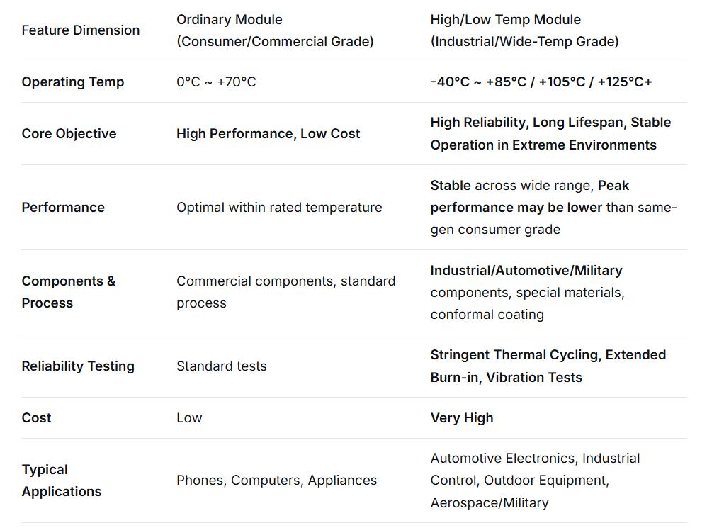
Summary Table

 differences between high and low temperature Linear modules and ordinary Linear modules

Conclusion:

The choice of module depends entirely on the application scenario. If your device operates in a climate-controlled indoor environment, ordinary Linear modules offer the best value. If your device needs to be deployed in a desert in summer, the Arctic in winter, a moving vehicle's engine bay, or the harsh environment of space, then high/low temperature Linear modules are fundamental to ensuring system survival and functionality. Their value far exceeds what performance specifications alone can measure.

At What Cooling Capacity Should You Choose a Screw-Type Air-Cooled Heat Pump

In the HVAC industry, screw-type air-cooled heat pumps are known for their stable performance and high efficiency, making them ideal for medium to large-scale cooling applications. However, they are not suitable for every project size. To truly benefit from their performance and efficiency, the system’s cooling capacity must reach a certain threshold — below which the investment may not be cost-effective, and above which the screw compressor’s advantages fully emerge.

Hstars industrial HVAC system screw chiller vs scroll chiller


Finding the Efficiency Threshold

The performance benefits of screw-type compressors become evident once the cooling load surpasses a specific level.
Compared with scroll compressors, a screw unit can handle larger capacities without multiple compressors running in parallel, reducing footprint, start-stop losses, and energy decay. Compared with reciprocating compressors, it offers higher energy efficiency and smoother capacity control under fluctuating loads.
This cooling capacity threshold marks the turning point where the system transitions from “overbuilt and uneconomical” to “efficient and well-matched.” Below it, you risk overspending; above it, you unlock the optimal balance between performance and cost.

Applications in Commercial Buildings

Once cooling capacity exceeds this threshold, the system adaptability of screw-type air-cooled heat pumps improves dramatically.
• In office buildings, their stepless slide-valve control can precisely follow cooling load variations during working hours.
• In three-star hotels or above, the low-noise operation of screw compressors ensures a quiet and comfortable environment.
• For medium-sized shopping centers, their robust pressure design handles complex piping systems effectively, minimizing leakage and improving reliability.

Applications in Industrial Facilities

In industrial environments, the benefits of screw-type heat pumps are even more pronounced:
• For electronics and precision instrument workshops, the rapid response and stable operation help maintain temperature consistency during intermittent processes.
• In food processing plants (such as dairy or bakery facilities), screw-type units support strict cold chain requirements with precise temperature control.
• For medium-sized data centers, the long maintenance cycle reduces downtime risks and enhances operational reliability.

When a Screw-Type Heat Pump Isn’t Ideal

If the cooling demand falls below this critical threshold—such as in convenience stores or small offices—a screw-type system may not be the right fit. Its higher initial cost and larger footprint can lead to unnecessary energy loss, the equivalent of “using a race car for city traffic.”
Conversely, for super-large facilities like massive commercial complexes or industrial parks, multiple screw units can meet the capacity demand, but centrifugal chillers often outperform them in full-load energy efficiency and total lifecycle cost.

Low-Temperature Environments

In regions where ambient temperatures are low and heating loads are high, screw-type air-cooled heat pumps with economizer (EVI) technology are recommended. They maintain excellent heating capacity at low temperatures, prevent defrost inefficiency, and ensure stable winter operation.

Conclusion

Screw-type air-cooled heat pumps are most suitable for medium-scale projects—where cooling demand exceeds a defined lower limit and where efficiency, stability, and adaptability matter most.
When selecting a unit, start by confirming your cooling load, then evaluate environmental factors such as noise, pressure, and temperature stability, along with your budget.
A properly matched screw system not only delivers optimal performance but also achieves long-term energy savings and operational reliability.


HCTE invites you to attend the 2025 Bangkok Auto Parts Exhibition | Booth V25, empowering the future of automobile intelligent manufacturing with precision testing technology

Deeply cultivating the core links of automobile intelligent manufacturing, HCTE will appear at the Southeast Asian industry event with innovative testing equipment


Dear industry partners and customers:

As the global automotive industry accelerates towards intelligence and greening, HCTE, a pioneer brand of H&H Group focusing on automotive testing technology, is using innovation to protect the quality of every car. From April 3 to 5, 2025, we will explore the future code of automobile manufacturing with you at booth V25 of the Bangkok Auto Parts Exhibition (TAPA 2025).


Why choose HCTE?

Because we know that the precision of each screw is related to safety; the strength of each weld carries trust.


Highlights of HCTE booth: Using technology to interpret the "zero defect" commitment

Airtightness test equipment: Building an invisible barrier for safety


Showing the world's leading multi-station airtightness detection system, covering key components such as new energy battery packs, fuel systems, cooling systems, and headlights, with a detection accuracy of 0.1Pa, helping you achieve "watertight" quality control.


Four-station automotive compressor hydrogen and nitrogen leak detection equipment


Vacuum chamber helium leak detection equipment: Redefining precision manufacturing standards

The fully automatic helium mass spectrometry leak detection solution designed for high value-added parts is suitable for precision components such as motor housings and sensors. The leak rate detection sensitivity is increased to 10⁻¹² mbar·L/s, providing "microscope-level" quality assurance for automotive core components.


Battery housing vacuum chamber helium leak detection equipment


Motor performance test bench: The efficient heart that drives future travel


From torque, temperature rise to energy efficiency ratio, HCTE's integrated motor test platform can be customized to adapt to various new energy motors, and the data acquisition speed is increased by 30%, helping customers shorten the R&D cycle and reduce trial and error costs.


Performance test equipment for winch reducer


Intelligent detection of welding process: making every weld a work of art

Combining visual recognition and laser sensing technology, real-time monitoring of welding strength and deformation parameters, eliminating the hidden dangers of false welding and leaking welding, and injecting "smart genes" into safety.


Eight-station automatic brazing machine


Why TAPA 2025 should not be missed?


The largest stage in Southeast Asia: Thailand accounts for 33% of the ASEAN automotive market share. The TAPA exhibition attracts more than 20,000 professional buyers, covering vehicle manufacturers, first-tier suppliers and after-sales markets.


Green transformation outlet: The Thai government plans to increase the proportion of electric vehicle production to 30% by 2030, and the demand for testing equipment has surged. HCTE technology precisely meets the needs of industrial upgrading.


Efficient docking opportunities: Booth V25 is located in the core exhibition area of ​​BITEC, adjacent to the main forum area, making it convenient for you to participate in the concurrent technical summit and dialogue with industry leaders.


Exhibition information:

Time: April 3-5, 2025 | 9:00-18:00

Location: BITEC Exhibition and Convention Center, Bangkok, Thailand (88 Bangna-Trad Road)

Booth: V25

We are ready and look forward to your arrival!