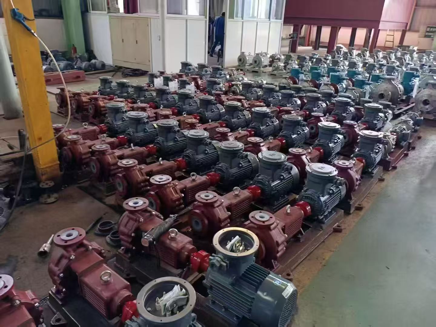
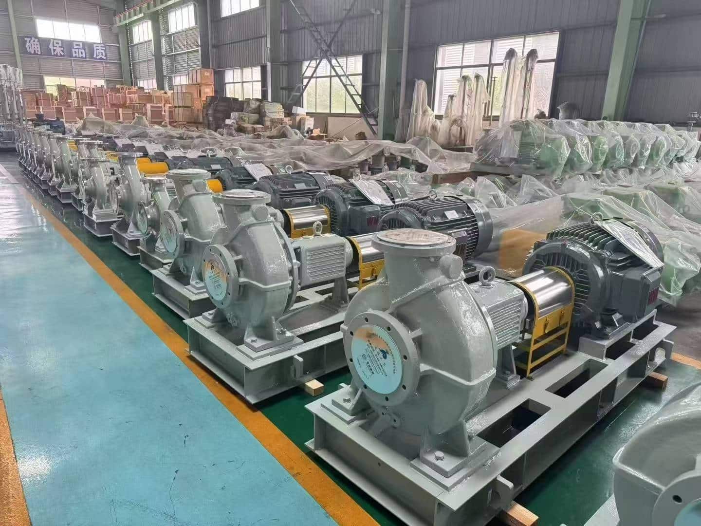
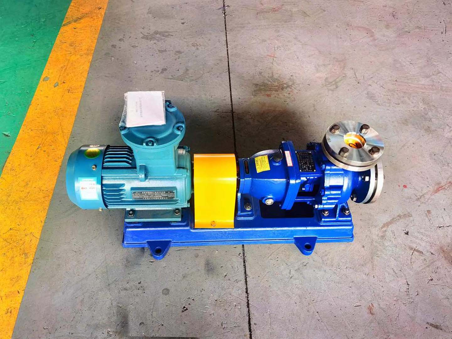
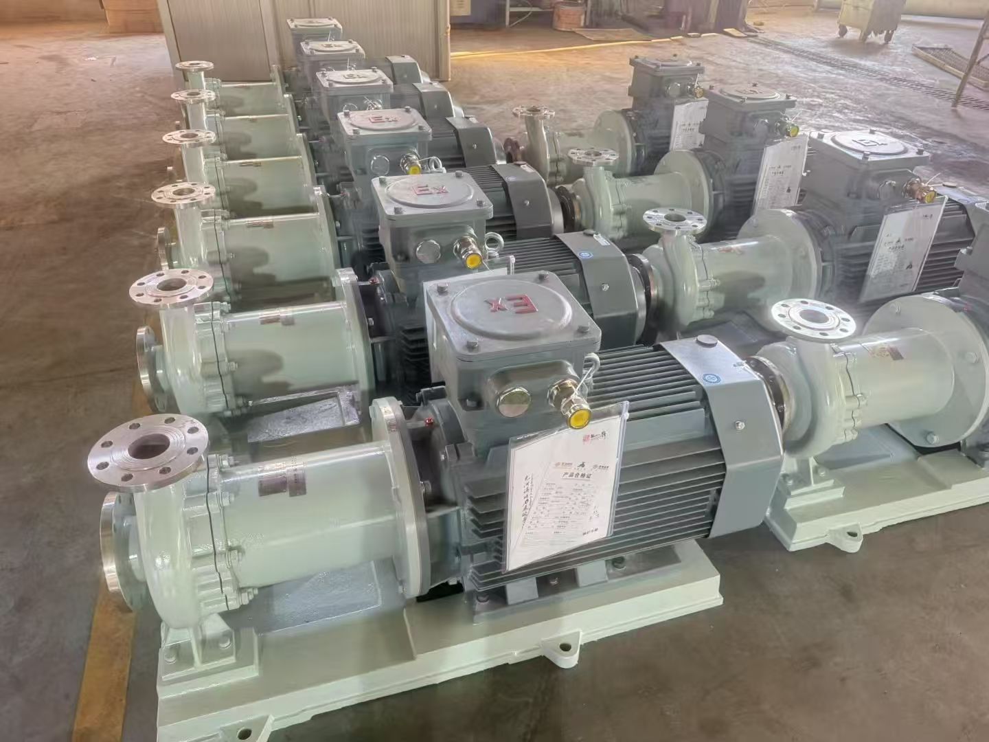
Protection Measures Against Demagnetization of Magnetic Drive Pumps


Regarding the demagnetization issue of magnetic drive pumps discussed in the last session, in this session, Anhui Shengshi Datang will provide some protective measures.

Improvement Measures for Magnetic Drive Pump Demagnetization

1. Improvement Approach

When improving the demagnetization situation of magnetic drive pumps, the primary focus is on enhancing the cooling aspect of lubrication to prevent the vaporization of the friction fluid, which leads to dry friction. However, it is also necessary to consider that the conveyed medium may contain vaporizable and volatile substances. According to the law of energy conservation, the velocity of the conveyed medium can be comprehensively reduced, and the static pressure can be increased to enhance the vaporization degree of the medium, thereby effectively preventing vaporization due to excessive temperature. Based on this improvement approach, comprehensive enhancements can be made to the impeller and bearing areas of the magnetic drive pump.

2. Improvement Measures

(1) The bearing of the magnetic drive pump needs to be changed from semi-hollow to fully hollow, and the return hole should be completely drilled through to become a through hole, effectively increasing the actual flow rate of the medium for cooling and lubrication.

(2) During installation, it is essential to ensure that the rotation directions of the spiral grooves match each other. The function of the spiral grooves is to provide flushing and lubrication for the medium. Therefore, the rotation direction of the spiral grooves must be clearly indicated to ensure smoother flow of the medium. During high-speed rotation, some heat will be carried away, thereby enhancing the cooling and lubrication effects on the bearings and thrust rings and promoting the formation of a liquid protective film during friction.

(3) The impeller section needs to be trimmed, but it must be ensured that the impeller efficiency remains unchanged. Trimming the impeller not only reduces the fluid flow velocity but also comprehensively enhances the vaporization degree of the medium through static pressure, improving the vaporization effect. At the same time, the operating range of the magnetic drive pump needs to be expanded to reduce the vibration impact of the process during operation.

(4) A protection device needs to be installed in the magnetic drive pump. During operation, if any component is overloaded or the inner magnetic rotor gets stuck in the "bearing seizure" condition, the protection device can cause it to automatically disengage, providing comprehensive protection for the magnetic drive pump.
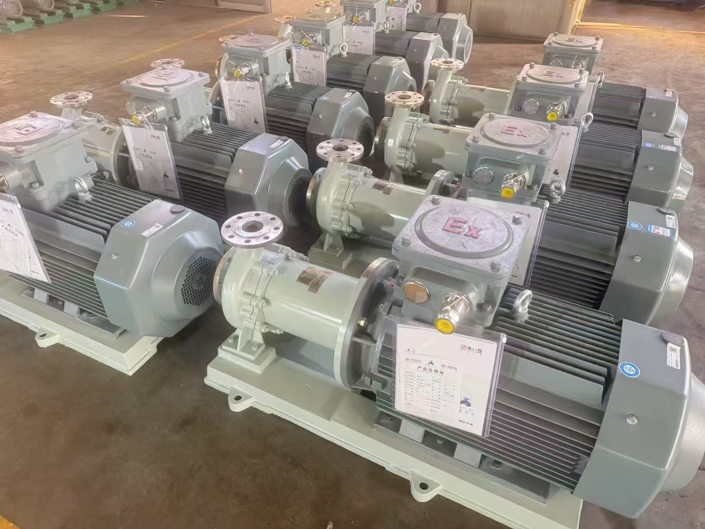
Operational Considerations for Magnetic Drive Pumps

To fundamentally resolve the demagnetization issue of magnetic drive pumps, in addition to comprehensive improvements, the following points must be noted during operation:

1. Before starting the magnetic drive pump, priming must be performed to ensure no air or gas remains inside the pump.

2. The bearings of the magnetic drive pump rely on the conveyed medium for cooling and lubrication. Therefore, it is essential to ensure that the magnetic drive pump does not run dry or that all medium is cleared, as this could cause bearing failure due to dry friction or a sudden significant temperature rise inside the pump, leading to demagnetization of the inner magnetic rotor.

3. If the conveyed medium contains particulate matter, a filter screen must be installed at the pump inlet to prevent excessive debris from entering the magnetic drive pump.

4. Components such as the rotor and crankshaft have strong magnetic properties. During installation and removal, the magnetic field scope must be fully considered. Otherwise, it may affect nearby electronic equipment. Therefore, installation and removal must be performed at a distance from electronic devices.

5. During operation of the magnetic drive pump, no objects should come into contact with the outer magnetic rotor to avoid damage and other issues.

6. The outlet valve must not be closed during the operation of the magnetic drive pump, as this could damage components such as the bearings and magnetic steel. If the pump continues to operate normally after the outlet valve is closed, this time must be controlled within 2 minutes to prevent demagnetization.

7. The inlet pipeline valve should not be used to control the flow rate of the medium, as this may cause cavitation.

8. After the magnetic drive pump has been in continuous operation for a certain period, it should be appropriately stopped. After confirming that the wear on the bearings and thrust rings is not severe, disassemble them to inspect the internal components. If minor issues are found in any components, replace them immediately.
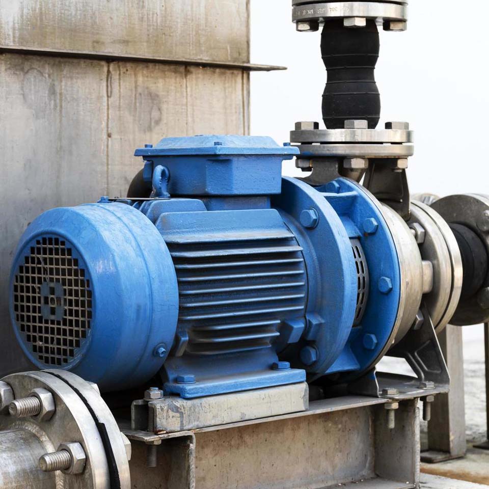
In addition to the above considerations, here are some supplementary points:

A. Root Cause: In-Depth Understanding of Demagnetization Mechanism

The magnetic coupler of a magnetic drive pump consists of an inner magnetic rotor and an outer magnetic rotor. When the inner magnetic rotor overheats due to insufficient cooling and lubrication, or when abnormal conditions (such as dry friction or cavitation) cause a sharp temperature rise, once the Curie temperature of permanent magnet materials like NdFeB (typically between 110°C - 150°C) is reached, their magnetism will sharply decline or even permanently disappear. Therefore, the ultimate goal of all measures is to ensure that the inner magnetic rotor always remains below a safe temperature.

B. Preventive Measures During Design and Selection (Source Control)

The following aspects are crucial when purchasing or improving magnetic drive pumps:

1. Selecting Appropriate Magnetic Material and Protection Grade:

a. Neodymium Iron Boron (NdFeB): High magnetic energy product, but relatively low Curie temperature and prone to corrosion. Must ensure complete encapsulation (e.g., stainless steel sleeve) and good cooling.

b. Samarium Cobalt (SmCo): Slightly lower magnetic energy product, but higher Curie temperature (can exceed 300°C), better thermal stability, and more corrosion-resistant. For high-temperature conditions or applications requiring high reliability, SmCo magnets should be prioritized.

c. Inquire with Suppliers: Clarify the magnet material, grade, and Curie temperature.

2. Providing Accurate Operating Parameters:

During selection, it is essential to provide the manufacturer with accurate medium characteristics (including composition, viscosity, solid particle content, and size), operating temperature, inlet pressure, flow range, etc. This helps the manufacturer select the most suitable pump type, materials, and cooling flow path design for your needs.

3. Consider Installing a Temperature Monitoring System:

a. Isolation Sleeve Temperature Monitoring: Install temperature sensors (e.g., PT100) on the outer wall of the isolation sleeve. Since the inner magnetic rotor temperature is difficult to measure directly, the isolation sleeve temperature is the most direct reflection. Setting high-temperature alarms and shutdown interlocks is the most effective automated means to prevent demagnetization.

b. Bearing Monitoring: Advanced magnetic drive pumps can be equipped with bearing wear monitors to provide early warnings before severe wear leads to temperature rise.

 

C. Key Supplementary Considerations in Operation and Maintenance

In addition to the mentioned priming, preventing dry running, and avoiding cavitation, the following should also be noted:

1. Minimum Continuous Stable Flow and Cooling Circuit:

a. Magnetic drive pumps have a minimum continuous stable flow. Operating below this flow rate means the heat carried away by the internal medium circulation is insufficient, leading to temperature buildup.

b. It is essential to ensure that the pump's cooling return line (if equipped) is unobstructed. This line not only provides bearing lubrication but is also a lifeline for cooling the inner magnetic rotor. This line must never be closed or blocked.

2. Avoid "Low Flow" Operation:

Prolonged operation near the low flow point results in low efficiency, with most of the work converted into heat, similarly causing medium temperature rise and increasing demagnetization risk. Ensure the pump operates within its efficient range.

3. System Pressure and Net Positive Suction Head (NPSH):

a. Ensure Sufficient Inlet Pressure: The mentioned increase in static pressure to enhance vaporization essentially means increasing the Available NPSH (NPSHa) to be significantly greater than the pump's Required NPSH (NPSHr). This is fundamental to preventing cavitation, as the vibration and localized high temperatures generated by cavitation pose a dual threat to magnetic drive pumps.

b. Monitor Inlet Filters: For media containing impurities, the inlet filter must be cleaned regularly. Clogging can cause inlet pressure drop, inducing cavitation.

4. Contingency Plans for Abnormal Conditions:

a. Power Interruption: If a factory experiences a sudden power outage followed by a quick restoration, be cautious as the medium in the system may have partially vaporized or the pump may have accumulated air. In such cases, follow the initial startup steps for inspection and priming; do not start directly.

b. Hot Medium Transfer: When conveying easily vaporizable media, consider insulating the inlet pipeline and even cooling the pump body (e.g., adding a cooling water jacket) to ensure the medium remains in liquid state upon entering the pump.

D. Deepening Maintenance and Inspection

1. Regular Disassembly Inspection:

In addition to checking bearing and thrust ring wear, focus on inspecting the isolation sleeve and inner magnetic rotor surfaces. Any scratches or wear points may indicate poor cooling or misalignment.

Check the magnetic strength of the inner magnetic rotor (using a Gauss meter), establish historical data records, and track its magnetic decay trend.

2. Management of Standby Pumps:

The inner magnetic rotor of a magnetic drive pump stored as a long-term standby might experience slight demagnetization due to surrounding stray magnetic fields or vibrations. Regularly rotate the pump and alternate its use.
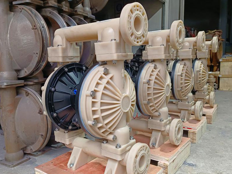
Troubleshooting and Handling Measures for Pneumatic Diaphragm Pump

In the previous blog, we discussed the common failures of pneumatic diaphragm pumps and analyzed their causes. Now, Anhui Shengshi Datang will guide you on how to troubleshoot these issues and what steps to take when encountering such situations.

Troubleshooting and Handling Measures

1. Air Pump Not Working

When it is found that the pneumatic diaphragm pump cannot start normally or stops immediately after starting, it should be inspected based on this symptom:

(1) First, check whether the connection points of the circuit are broken. If the circuit is damaged or the connections are loose, replace the wires in the circuit or reinforce the connections promptly to restore the equipment to operation and improve the stability of the air pump.

(2) If parts that frequently experience friction show significant wear or have aged and lost elasticity, consider replacing them to enhance the stability of the system operation.

2. Inlet/Outlet Pipeline Blockage

If the issue with the air pump is determined to be in the inlet/outlet pipeline, and the pump cannot operate normally due to pipeline blockage, inspect and address it based on the following symptoms:

Common Faults Cause Analysis Handling Measures
Insufficient pressure supply or pressure increase in the diaphragm pump Improper adjustment of the pneumatic diaphragm pump pressure regulating valve or poor air quality; malfunction of the pressure regulating valve; malfunction of the pressure gauge Adjust the pressure valve to the required pressure; inspect and repair the pressure regulating valve; inspect or replace the pressure gauge
Pressure drop in the diaphragm pump Insufficient oil replenishment by the oil replenishment valve; insufficient feed or leakage in the feed valve; oil leakage from the plunger seal Repair the oil replenishment valve; inspect and repair the sealing parts; refill with new oil
Reduced flow rate in the diaphragm pump Pump body leakage or diaphragm damage; rupture of the inlet/outlet valve; diaphragm damage; low speed that cannot be adjusted Inspect and replace the sealing gasket or diaphragm; inspect, repair, or replace the feed valve; replace the diaphragm; inspect and repair the control device, adjust the rotation speed

(1) Disassemble and clean the internal pipelines of the equipment to remove various impurities attached to the pipelines. Improve the cleanliness of the pipe walls and enhance the stability of the equipment operation.

(2) Strengthen the management of medium materials to ensure that materials do not mix due to sharing. Ideally, use one device for pumping a specific material. If the same equipment must be used, clean the pipelines promptly to avoid air pump pipeline blockages and improve the stability of the air pump's working condition.

3. Severe Ball Seat Wear

If ball seat wear is confirmed through inspection, troubleshoot using the following measures:

(1) First, confirm whether its sealing performance can support normal equipment operation. If the ball seat wear is too severe to determine, replace the ball seat to maintain the fit between the ball seat and the ball and avoid poor sealing.

(2) Since friction between the ball seat and the ball is inevitable, monitor the operating condition of the ball seat in real time during daily operations to enhance the overall stability of the equipment.

4. Severe Ball Valve Wear

If ball valve wear is confirmed through inspection, and the wear is severe, troubleshoot using the following measures:

(1) Replace severely damaged ball valves. If no spare ball valve is available, temporarily use a ball bearing as a substitute and replace it with a matching ball valve afterward.

(2) Media with excessively high viscosity will increase the resistance of the ball, preventing flexible operation. In this case, clean the ball valve and base to ensure smooth transportation and improve the stability of the equipment operation.

5. Irregular Air Pump Operation

For issues related to irregular air pump operation, inspect and address them based on the specific symptoms:

(1) Replace severely worn ball valves to improve structural stability.

(2) If the diaphragm is damaged, replace it promptly to enhance the reliability of the system's processing.

(3) If the issue is due to limitations of the preset system, upgrade the system to improve the stability of the equipment system operation.

6. Insufficient Air Supply Pressure

For problems caused by insufficient air supply pressure, inspect and troubleshoot using the following measures:

(1) Confirm whether the equipment operating system is stable and check the system pressure condition. If it meets the requirements, continue using it; otherwise, debug it as soon as possible.

(2) To maintain the volume and cleanliness of compressed air, add an air filtration device and improve the purity of the compressed air to maintain the equipment output rate and enhance system stability.


Analysis of the Working Principle and Causes of Cavitation in Centrifugal Pumps

Working Principle of Centrifugal Pumps

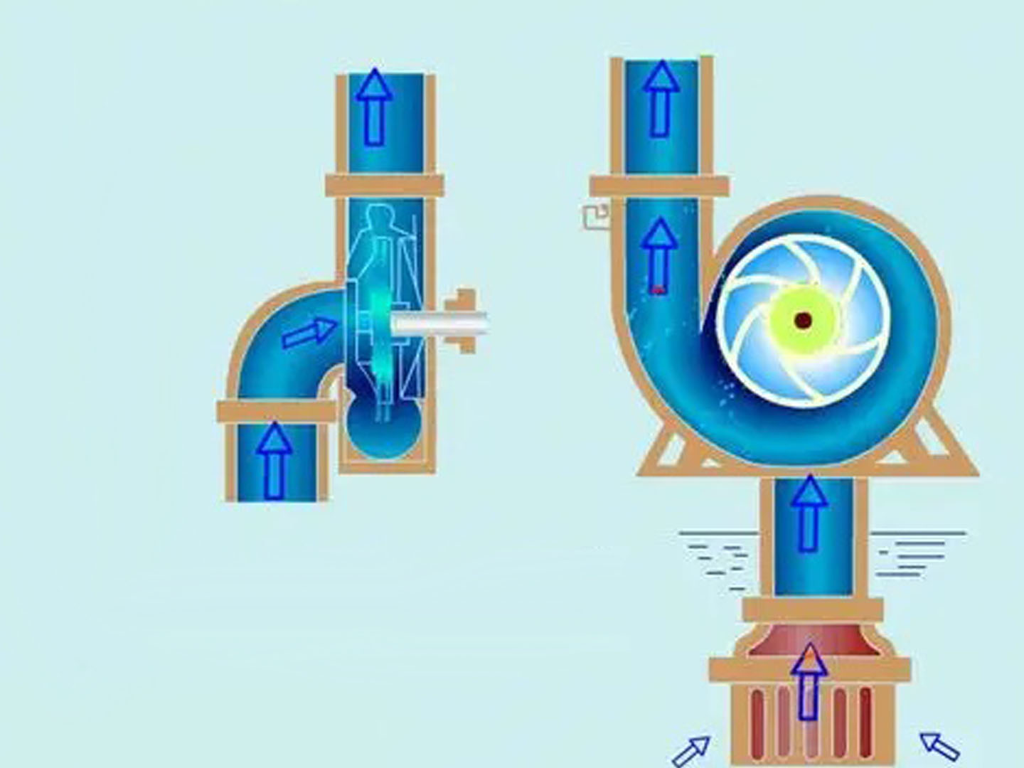
The working principle of centrifugal pumps is based on the action of centrifugal force. When the impeller rotates at high speed, the liquid is thrown from the center of the impeller to the outer edge under the influence of centrifugal force, thereby gaining kinetic energy and pressure energy. The specific working process is as follows:

1.Liquid enters the central area of the impeller through the pump's suction inlet.

2.The rotation of the impeller generates centrifugal force, causing the liquid to move from the center of the impeller to the outer edge along the blade passages.

3.The liquid gains kinetic energy and pressure energy within the impeller and is then discharged into the pump casing.

4.Inside the pump casing, part of the liquid's kinetic energy is converted into pressure energy, and the liquid is ultimately discharged through the outlet.

During the operation of a centrifugal pump, the impeller does work by converting mechanical energy into the energy of the liquid. As the liquid flows through the impeller, both its pressure and velocity increase. According to Bernoulli's equation, the increase in the total energy of the liquid is primarily manifested as an increase in pressure energy, enabling the centrifugal pump to transport the liquid to a higher elevation or overcome greater system resistance.

It is important to note that the prerequisite for the normal operation of a centrifugal pump is that the pump cavity must be filled with liquid. This is because centrifugal force can only act on liquids and not on gases. If air is present in the pump cavity, the pump will be unable to build up pressure normally, resulting in "vapor lock," which ultimately leads to cavitation.

Analysis of Causes for Centrifugal Pump Cavitation

 1.Inadequate Inlet Medium or Insufficient Inlet Pressure

Inadequate inlet medium is one of the most common causes of centrifugal pump cavitation. The following situations may lead to insufficient inlet medium:

a. Low Liquid Level: When the liquid level in a pool, tank, or storage container falls below the pump's suction pipe or the minimum effective level, the pump may draw in air instead of liquid, resulting in cavitation.

b. Excessive Suction Lift: For non-self-priming centrifugal pumps, if the installation height exceeds the allowable suction lift, even if the suction pipe is immersed in the liquid, the pump will be unable to draw the liquid up, leading to a lack of liquid inside the pump. According to physical principles, the theoretical maximum suction lift for non-self-priming centrifugal pumps is approximately 10 meters of water column (atmospheric pressure value). However, considering various losses, the actual suction lift is typically below 6-7 meters.

c. Insufficient Inlet Pressure: In applications requiring positive inlet pressure, if the provided inlet pressure is lower than the required value, the pump may experience inadequate liquid supply, causing cavitation.

d. Poor System Design: In some system designs, if the suction pipeline is too long, the pipe diameter is too small, or there are too many bends, the pipeline resistance increases, reducing the inlet pressure and preventing the centrifugal pump from drawing liquid properly.

Case studies show that approximately 35% of centrifugal pump failures in the petrochemical industry are caused by inadequate inlet medium or insufficient inlet pressure. This issue is particularly common in oil transportation systems due to the high viscosity and vapor pressure of oil products.


 2.Blockage in the Inlet Pipeline

Blockage in the inlet pipeline is another common cause of centrifugal pump cavitation. Specific manifestations include:

a. Clogged Screens or Filters: During long-term operation, screens or filters in the inlet pipeline may become gradually blocked by impurities or sediments, restricting liquid flow.

b. Scale Formation Inside the Pipeline: Particularly when handling hard water, water with high calcium and magnesium ion content, or specific chemical liquids, scale or crystalline deposits may form on the inner walls of the pipeline, reducing the effective diameter over time.

c. Foreign Object Entry: Accidental entry of objects such as leaves, plastic bags, or aquatic plants into the suction pipeline can block elbows or valves, obstructing liquid flow.

d. Partially Closed Valves: Operational errors, such as failing to fully open valves in the suction pipeline, or internal valve malfunctions, can also lead to insufficient flow.

e. Foot Valve Failure: In systems equipped with foot valves, if the foot valve malfunctions (e.g., spring deformation or sealing surface damage), it can affect the pump's ability to draw liquid properly.

Statistical data indicate that approximately 25% of centrifugal pump cavitation cases in municipal water supply and drainage systems are caused by inlet pipeline blockages. This issue is especially common in wastewater treatment systems with high levels of suspended solids.


 3.Incomplete Air Removal from the Pump Cavity

Incomplete air removal from the pump cavity is a significant cause of centrifugal pump cavitation. Key manifestations include:

a. Inadequate Priming Before Initial Startup: After initial installation or prolonged shutdown, centrifugal pumps must be primed to remove air from the pump body. If priming is insufficient, residual air can prevent the pump from establishing normal working pressure.

b. Insufficient Self-Priming Capability: Non-self-priming centrifugal pumps cannot expel air on their own and rely on external priming. While some self-priming pumps have a certain self-priming capability, improper startup methods or excessive self-priming height can lead to poor air expulsion.

c. Air Leaks in the Pipeline System: Minor cracks in suction pipeline connections, sealing points, or aging pipes can allow air to enter the system under negative pressure. This is particularly hazardous because even if the pump is initially primed correctly, air can accumulate over time, eventually causing cavitation.

d. Seal Failure: Worn or improperly installed shaft seals (e.g., mechanical seals or packing seals) can allow external air to enter the pump, especially when the suction side pressure is below atmospheric pressure.

In industrial applications, approximately 20% of centrifugal pump cavitation cases are caused by incomplete air removal from the pump cavity. This issue is particularly common during initial startup after installation or maintenance.


 4.Other Causes

In addition to the main causes mentioned above, other factors can also lead to centrifugal pump cavitation:

a. Liquid Vaporization: When handling high-temperature or highly volatile liquids, if the suction pipeline pressure falls below the liquid’s saturation vapor pressure at that temperature, the liquid may vaporize, forming bubbles. This can prevent the pump from drawing liquid or cause cavitation.

b. Operational Errors: Human factors, such as incorrect valve operation or failure to follow startup procedures, can lead to pump cavitation.

c. Control System Malfunctions: In automated control systems, failures in level sensors, pressure sensors, or errors in PLC programming logic may cause the pump to start or operate under inappropriate conditions, resulting in cavitation.

d. Power or Motor Issues: Incorrect power phase sequence causing motor reversal can prevent the pump from drawing liquid properly. Voltage instability causing motor speed fluctuations can also disrupt normal pump operation.

e. Temperature Effects: In extreme environmental conditions, such as cold regions, inadequate insulation may cause liquid in the pipeline to freeze, obstructing flow. In high-temperature environments, liquids may vaporize, forming vapor locks.

Research indicates that these other causes account for approximately 20% of centrifugal pump cavitation cases. Although the proportion is relatively small, they can be significant factors in specific scenarios or conditions and should not be overlooked.

Comprehensive Guide to Chemical Centrifugal Pumps From Features to Installation

Comprehensive Guide to Chemical Centrifugal Pumps: From Features to Installation


1.Overview of Chemical Centrifugal Pumps

Chemical centrifugal pumps, as reliable assistants in the chemical industry, have gained widespread popularity due to their outstanding performance characteristics, such as wear resistance, uniform water output, stable operation, low noise, easy adjustment, and high efficiency. Their working principle involves the generation of centrifugal force when the impeller rotates while the pump is filled with water. This force pushes the water in the impeller channels outward into the pump casing. Subsequently, the pressure at the center of the impeller gradually decreases until it falls below the pressure in the inlet pipe. Under this pressure differential, water from the suction pool continuously flows into the impeller, enabling the pump to sustain water suction and supply. With the growing demand for chemical centrifugal pumps across various industries, it is essential to delve into their technical details. Next, Anhui Shengshi Datang will explore 20 technical questions and answers about chemical centrifugal pumps with you, unveiling the technical mysteries behind them.


2.Performance Characteristics of Chemical Centrifugal Pumps

Chemical centrifugal pumps are highly favored for their wear resistance, uniform water output, and other features. They possess multiple characteristics, including adaptability to chemical process requirements, corrosion resistance, tolerance to high and low temperatures, resistance to wear and erosion, reliable operation, minimal or no leakage, and the ability to transport liquids in critical states.


3.Technical Details of Chemical Centrifugal Pumps

a. Definition and Classification

Chemical centrifugal pumps are devices that generate centrifugal force through impeller rotation and can be classified into vane pumps, positive displacement pumps, etc. Based on their working principles and structures, chemical pumps are categorized into vane pumps, positive displacement pumps, and other forms. Vane pumps utilize the centrifugal force generated by impeller rotation to enhance the mechanical energy of liquids, while positive displacement pumps transport liquids by altering the working chamber volume. Additionally, there are special types like electromagnetic pumps, which use electromagnetic effects to transport conductive liquids, as well as jet pumps and airlift pumps that utilize fluid energy to convey liquids.


b. Advantages and Performance Parameters

Centrifugal pumps offer high flow rates, simple maintenance, and core metrics such as output power and efficiency. Centrifugal pumps exhibit several notable advantages in application. First, their single-unit output provides a large and continuous flow without pulsation, ensuring smooth operation. Second, their compact size, lightweight design, and small footprint reduce costs for investors. Third, the simple structure, minimal vulnerable parts, and long maintenance intervals minimize operational and repair efforts. Furthermore, centrifugal pumps feature excellent adjustability and reliable operation. Notably, they require no internal lubrication, ensuring the purity of the transported fluid without contamination from lubricants.


 c. Types of Losses and Efficiency

Main hydraulic losses include vortex, resistance, and impact losses, with efficiency being the ratio of effective power to shaft power. Hydraulic losses in centrifugal pumps, also known as flow losses, refer to the difference between theoretical head and actual head. These losses occur due to friction and impact during liquid flow within the pump, converting part of the energy into heat or other forms of energy loss.

Hydraulic losses in centrifugal pumps primarily consist of three components: vortex loss, resistance loss, and impact loss. These combined effects create the difference between theoretical and actual head. The efficiency of a centrifugal pump, also called mechanical efficiency, is the ratio of effective power to shaft power, reflecting the extent of energy loss during operation.


d. Speed and Power

Speed affects flow rate and head, with power measured in watts or kilowatts. The speed of a centrifugal pump refers to the number of rotations the pump rotor completes per unit time, measured in revolutions per minute (r/min). The power of a centrifugal pump, or the energy transmitted to the pump shaft by the prime mover per unit time, is also known as shaft power, typically measured in watts (W) or kilowatts (KW).


e. Head and Flow Rate

When speed changes, flow rate and head vary according to square or cubic relationships. Adjusting the speed of a centrifugal pump alters its head, flow rate, and shaft power. For unchanged media, the ratio of flow rate to speed exceeds the speed itself, while the ratio of head to speed equals the square of the speed ratio. Meanwhile, the ratio of shaft power to speed equals the cube of the speed ratio.


f. Number of Blades and Materials

The number of blades typically ranges from 6 to 8, with materials requiring corrosion resistance and high strength. The number of blades in a centrifugal pump impeller is a critical parameter directly affecting pump performance. Generally, the blade count is set based on specific applications and needs, ensuring efficient and stable operation. Common manufacturing materials include gray cast iron, acid-resistant silicon iron, alkali-resistant aluminum cast iron, chromium stainless steel, etc.


g. Pump Casing and Structure

The pump casing collects liquid and increases pressure, with common structures including horizontal split-type designs. The pump casing plays a vital role in centrifugal pumps. It not only collects liquid but also gradually reduces liquid velocity through specific channel designs. This process effectively converts part of the kinetic energy into static pressure, enhancing liquid pressure while minimizing energy loss due to oversized channels. Common pump casing structures include horizontal split-type, vertical split-type, inclined split-type, and barrel-type designs.


With the continuous updates in process technology for chemical enterprises, stricter demands are placed on the stable operation of chemical centrifugal pumps. These pumps play a crucial role in the chemical industry, where their performance stability directly impacts the smoothness of the entire production process. Therefore, a deep understanding and rational selection of pump casing support forms are essential for ensuring the stable operation of chemical centrifugal pumps.

Embarking on a journey of thousands of miles with a strong wind, bearing the weight of a thousand pounds and striving ahead once more


Visiting Liang Zhiquan, the Product Director of QSTECH CO., LTD. (QSTECH).


In the past few years, LED all-in-one machines have achieved significant success across various industries and sectors. Especially in areas like advertising, commerce, conferences, education, theaters, stadiums, exhibitions, and entertainment, LED all-in-one machines have become the mainstream display devices. However, there's one company that not only leads in the domestic LED display field but also holds the record for the highest market share in the LED integrated display industry in China*. This company is QSTECH CO., LTD. (referred to as "QSTECH" below). The editorial team of "LED display" had the privilege of interviewing Liang Zhiquan, the Product Director of QSTECH, to delve into the secrets behind QSTECH's success in the LED integrated display field.


Craftsmanship Creates Quality, Setting the Benchmark for Excellence


In recent years, QSTECH's LED all-in-one machines have consistently stood out due to their outstanding product quality and continuous innovation, earning the favor of consumers in the market. Liang Zhiquan explained, "QSTECH offers LED all-in-one machines with 16:9 aspect ratios in models ranging from 120 to 220 inches, with resolutions such as 2K and 4K; as well as ultra-wide 32:9 screens in models like 199, 249, and 299 inches with 4K resolution." The core strengths of QSTECH's LED all-in-one machines lie in their convenience through an intelligent system that introduces new application methods, energy efficiency and environmental friendliness through advanced power and system design, and exceptional display quality achieved through meticulous calibration using QSTECH's systems.


QSTECH places a strong emphasis on technological innovation and research and development, boasting a team of highly skilled engineers who continuously explore and study new technologies. They consistently launch high-quality LED integrated display products that meet the market's demands. "For four consecutive years, we have ranked first in both shipments and sales in the LED integrated display industry*," Liang Zhiquan proudly stated. In various industries and scenarios, such as large and medium-sized conference venues, exhibition halls, and small briefing rooms, QSTECH's LED all-in-one machines have been widely utilized. Liang Zhiquan expressed his pride, stating that QSTECH's products are highly integrated and user-friendly, evident in cases like the transformation of a crucial meeting room for a certain enterprise, where QSTECH's LED integrated display meets all application needs with a single power cable.


Seizing Opportunities, Planning Development, and Drawing a New Chapter


The era of the pandemic has accustomed people to remote work, including remote meetings and training among teams. In the post-pandemic era, communication, training, and other activities within and between companies are expected to experience explosive growth. With the diversification of businesses, the demand for large-sized, user-friendly LED all-in-one machines has surged for various local and remote meetings, trainings, and more. Liang Zhiquan believes that LED all-in-one machines will gradually replace traditional displays in spaces below 10 square meters or within spaces of 60 to 300 square meters, as the cost of LED all-in-one machines decreases, driving an accelerated rate of replacement.


QSTECH is poised to respond to this trend by focusing on customer needs, deeply understanding the current market, researching the demands of various stakeholders, and considering factors such as touch experience and visual quality to create products that align with user preferences. Liang Zhiquan noted, "QSTECH's integrated design combines receiver cards, power supplies, and interface boards on a single card with wireless connections. This design shift from 'soft connections' to 'hard connections' eliminates issues caused by aging cables or loose connections, enhancing product stability and reliability." According to related data, QSTECH has held the top market share in the Chinese LED integrated display industry from 2019 to 2022, and updated data shows that its market share exceeded 40% in Q1 of 2023*. Additionally, QSTECH boasts a highly skilled team that possesses deep understanding and mastery of their products, thus establishing a strong brand image and reputation in the market. This marks the beginning of a new chapter of high-quality development for QSTECH's LED all-in-one machines.


Forging Ahead on a New Journey, Riding the Momentum toward the Future


The underlying logic of LED all-in-one machines has evolved from complex engineering to user-friendly integration and high levels of integration. In the future, LED all-in-one machines are expected to appear in even more industries and application scenarios. Wherever a large-sized display is needed, LED all-in-one machines will have a presence. The convenience, energy efficiency, and exceptional display quality of LED all-in-one machines have transformed them from mere LED screens into versatile carriers of various applications. QSTECH is prepared to unleash its potential in the new journey of the future.


It's important to note that while LED all-in-one machines have proliferated like mushrooms after rain, not all products on the market are of high quality. Some products labeled as LED all-in-one machines have provided users with subpar experiences, causing good products to not spread as quickly as expected. Liang Zhiquan suggests that the industry should promptly improve the standards for LED all-in-one machines, ensuring that users have access to safe, user-friendly, and visually appealing LED integrated display products. In the future, QSTECH will further enhance technological innovation and research and development to provide users with higher quality, more advanced LED display products and services.


Lastly, Liang Zhiquan pointed out that Micro LED all-in-one machines are currently conceptual products. True full-process Micro LED all-in-one machines still face many technical challenges and cost pressures. However, looking at the development trend from a technological perspective and based on scenarios, there is significant market potential for Micro LED all-in-one machines in the future. Liang Zhiquan is confident that QSTECH will embrace the opportunities and challenges of the LED integrated display market and will surely make remarkable progress in the development of Micro LED all-in-one machines.


Start your extraordinary projects today!


Explain the working principle of magnetic pumps and the causes of demagnetization.

Magnetic pumps are commonly used pumps, and demagnetization is a relatively frequent cause of damage. Once demagnetization occurs, many people may find themselves at a loss, which could lead to significant losses in work and production. To prevent such situations, Anhui Shengshi Datang will briefly explain today why magnetic pumps experience demagnetization.


1. Magnetic Pump Structure and Principle

1.1 Overall Structure

The main components of a magnetic pump's overall structure include the pump, the motor, and the magnetic coupler. Among these, the magnetic coupler is the key component, encompassing parts such as the containment shell (isolating can) and the inner and outer magnetic rotors. It significantly impacts the stability and reliability of the magnetic pump.


1.2 Working Principle

A magnetic pump, also known as a magnetically driven pump, operates primarily on the principle of modern magnetism, utilizing the attraction of magnets to ferrous materials or the magnetic force effects within magnetic cores. It integrates three technologies: manufacturing, materials, and transmission. When the motor is connected to the outer magnetic rotor and the coupling, the inner magnetic rotor is connected to the impeller, forming a sealed containment shell between the inner and outer rotors. This containment shell is firmly fixed to the pump cover, completely separating the inner and outer magnetic rotors, allowing the conveyed medium to be transmitted into the pump in a sealed manner without leakage. When the magnetic pump starts, the electric motor drives the outer magnetic rotor to rotate. This creates attraction and repulsion between the inner and outer magnetic rotors, driving the inner rotor to rotate along with the outer rotor, which in turn rotates the pump shaft, accomplishing the task of conveying the medium. Magnetic pumps not only completely solve the leakage problems associated with traditional pumps but also reduce the probability of accidents caused by the leakage of toxic, hazardous, flammable, or explosive media.


1.3 Characteristics of Magnetic Pumps

(1) The installation and disassembly processes are very simple. Components can be replaced anywhere at any time, and significant costs and manpower are not required for repair and maintenance. This effectively reduces the workload for relevant personnel and substantially lowers application costs.

(2) They adhere to strict standards in terms of materials and design, while requirements for technical processes in other aspects are relatively low.

(3) They provide overload protection during the conveyance of media.

(4) Since the drive shaft does not need to penetrate the pump casing, and the inner magnetic rotor is driven solely by the magnetic field, a completely sealed flow path is truly achieved.

(5) For containment shells made of non-metallic materials, the actual thickness is generally below about 8 mm. For metallic containment shells, the actual thickness is below about 5 mm. However, due to the thick inner wall, they will not be punctured or worn through during the operation of the magnetic pump.


2. Main Causes of Demagnetization in Magnetic Pumps

2.1 Operational Process Issues

Magnetic pumps represent relatively new technology and equipment, requiring high technical proficiency during application. After demagnetization occurs, operational and process aspects should first be investigated to rule out problems in these areas. The investigation content includes six parts:

(1) Check the magnetic pump's inlet and outlet pipelines to ensure there are no issues with the process flow.

(2) Check the filter device to ensure it is free of any debris.

(3) Perform priming and venting of the magnetic pump to ensure no excess air remains inside.

(4) Check the liquid level in the auxiliary feed tank to ensure it is within the normal range.

(5) Check the operator's actions to ensure no errors occurred during operation.

(6) Check the maintenance personnel's operations to ensure they complied with relevant standards during maintenance.


2.2 Design and Structural Issues

After thoroughly investigating the above six aspects, a comprehensive analysis of the magnetic pump's structure is necessary. The sliding bearings play a cooling role when the magnetic pump conveys the medium. Therefore, it is essential to ensure sufficient medium flow rate to effectively cool and lubricate the gap between the containment shell and the sliding bearings, and the friction between the thrust ring and the shaft. If there is only one return hole for the sliding bearings and the pump shaft is not interconnected with the return hole, the cooling and lubrication effect can be reduced. This prevents complete heat removal and hinders maintaining a good state of liquid friction. Ultimately, this can lead to seizure of the sliding bearings (bearing lock-up). During this process, the outer magnetic rotor continues to generate heat. If the inner magnetic rotor's temperature remains within the limit, the transmission efficiency decreases but can potentially be improved. However, if the temperature exceeds the limit, it cannot be remedied. Even if it cools down after shutdown, the reduced transmission efficiency cannot recover to its original state, eventually causing the magnetic properties of the inner rotor to gradually diminish, leading to demagnetization of the magnetic pump.


2.3 Medium Properties Issues

If the medium conveyed by the magnetic pump is volatile, it can vaporize when the internal temperature rises. However, both the inner magnetic rotor and the containment shell generate high temperatures during operation. The area between them also generates heat due to being in a vortex state, causing the internal temperature of the magnetic pump to rise sharply. If there are issues with the magnetic pump's structural design, affecting the cooling effect, then when the medium is delivered into the pump, it may vaporize due to the high temperature. This causes the medium to gradually turn into gas, severely affecting the pump's operation. Additionally, if the static pressure of the conveyed medium within the magnetic pump is too low, the vaporization temperature decreases, inducing cavitation. This can halt the medium conveyance, ultimately causing the magnetic pump bearings to burn out or seize due to dry friction. Although the pressure at the impeller varies during operation, centrifugal force effects can cause very low static pressure at the pump inlet. When the static pressure falls below the vapor pressure of the medium, cavitation occurs. When the magnetic pump contacts the cavitating medium, if the cavitation scale is small, it might not significantly affect the pump's operation or performance noticeably. However, if the medium's cavitation expands to a certain scale, a large number of vapor bubbles form inside the pump, potentially blocking the entire flow path. This stops the flow of medium inside the pump, leading to dry friction conditions due to the ceased flow. If the pump's structural design results in an inadequate cooling effect, the containment shell temperature can become excessively high and cause damage, subsequently increasing the temperature of both the medium and the inner magnetic rotor.

Prevention Measures for Centrifugal Pump Cavitation


In the previous section, we discussed the causes of centrifugal pump cavitation. Below, Anhui Shengshi Datang will introduce measures to prevent centrifugal pump cavitation.

1. Improvements in Design and Materials

From the perspectives of design and materials, the following measures can be taken to prevent or mitigate the hazards of centrifugal pump cavitation:

A. Gap Optimization Design: Appropriately increase the clearance between moving parts, especially between the impeller and the pump casing, and between the seal ring and the shaft, to reduce the risk of seizing due to thermal expansion. Research shows that increasing the standard clearance by 15%-20% can significantly reduce the probability of seizing during cavitation, with minimal impact on pump efficiency.

B. Material Selection and Treatment:

  a. Perform tempering heat treatment on the pump shaft to improve its hardness and wear resistance, reducing deformation and wear during cavitation.

  b. Select materials with low thermal expansion coefficients, such as stainless steel or special alloys, to minimize clearance changes caused by thermal expansion.

  c. Apply wear-resistant coatings like hard alloy or use ceramic materials for key friction parts such as seal rings to enhance wear resistance.

C. Sealing System Improvements:

  a. Use mechanical seals that do not rely on the pumped medium for lubrication, such as gas-lubricated mechanical seals or double mechanical seals.

 b. Configure external lubrication systems to provide lubrication for the seal faces even when the pump is cavitating.

 c. For packing seals, use self-lubricating packing, such as composite packing containing PTFE.


D. Bearing System Optimization:

 a. Use enclosed self-lubricating bearings to reduce dependence on external cooling.

 b. Add independent cooling systems for bearings to ensure normal bearing temperature is maintained even during pump cavitation.

 c. Select bearings and lubricants with higher temperature tolerance.

E. Pump Cavity Design Improvements:

 a. For special applications, design a water storage space so that the pump can maintain a minimum liquid volume even during short-term water shortage.

 b. Self-priming pumps are typically designed with a larger pump cavity volume and specialized gas-liquid separation devices, allowing them to better handle short-term cavitation.

Practice shows that reasonable design and material selection can reduce the risk of damage during centrifugal pump cavitation by over 50%, while also extending the overall service life of the equipment.

2. Application of Monitoring and Control Systems

Modern monitoring and control technologies provide effective means to prevent centrifugal pump cavitation:

A. Cavitation Detection Systems:

 a. Flow Monitoring: Install a flow meter at the pump outlet to automatically alarm or shut down the pump when the flow rate falls below a set value.

 b. Current Monitoring: Motor load decreases during cavitation, leading to a significant drop in current; cavitation can be detected by monitoring current changes.

 c. Pressure Monitoring: A sudden drop or increased fluctuation in outlet pressure is a key indicator of cavitation.

 d. Temperature Monitoring: Abnormal temperature rises in mechanical seals, bearings, or the pump body can indirectly reflect the cavitation state.

B. Liquid Level Control Systems:

 a. Install level sensors in water tanks, sumps, and other intake facilities to automatically stop the pump when the level falls below a safe value.

 b. For special occasions, set up dual-level protection: low-level alarm and very low-level forced pump shutdown.

 c. Use non-contact level gauges (e.g., ultrasonic, radar) to avoid potential jamming issues associated with traditional float switches.

C. Integrated Intelligent Control Systems:

 a. Integrate multiple parameters (flow, pressure, temperature, level) into a PLC or DCS system to more accurately identify cavitation status through logical judgment.

 b. Set up two levels of protection: cavitation warning and cavitation alarm. The system can attempt to automatically adjust operating conditions during a warning and force a shutdown during an alarm.

 c. Use expert systems or artificial intelligence technology to predict potential cavitation risks in advance through historical data analysis.

D. Remote Monitoring and Management:

 a. Utilize IoT technology to achieve remote monitoring of pump stations, enabling timely detection of abnormalities.

 b. Establish fault prediction models to provide early warnings of potential cavitation risks through big data analysis.

 c. Set up automatic recording and reporting systems to log changes in operating parameters, providing a basis for fault analysis.

Data shows that centrifugal pumps equipped with modern monitoring and control systems experience over 85% fewer cavitation incidents compared to traditional equipment, with significantly reduced maintenance costs. The value of these systems is particularly evident in unattended pump stations.


3. Operating Procedures and Maintenance Management

Scientific operating procedures and maintenance management are crucial links in preventing centrifugal pump cavitation:

A. Pre-Startup Checks and Preparation:

 a. Confirm that valves on the suction line are fully open and filters are not clogged.

 b. Check the sealing of the pump casing and pipelines to ensure there are no air leakage points.

 c. Ensure the pump is fully primed and air is completely vented before the first startup or after a prolonged shutdown.

 d. Manually rotate the pump shaft several turns to ensure it rotates flexibly without abnormal resistance.

B. Correct Startup and Shutdown Procedures:

 a. Open the suction valve first, then the discharge valve, avoiding starting against a closed discharge valve.

 b. For large pumps, start with the discharge valve slightly open, then fully open it once operation stabilizes.

 c. When stopping the pump, close the discharge valve first, then the motor, and finally the suction valve to prevent backflow and water hammer.

 d. Drain liquid from the pump casing promptly after shutdown in cold winter regions to prevent freezing.

C. Monitoring and Management During Operation:

 a. Establish an operating log system to regularly record parameters such as flow, pressure, temperature, and current.

 b. Implement an inspection round system to promptly detect abnormal noise, vibration, or leaks.

 c. Avoid prolonged operation at low flow rates; install a minimum flow bypass line if necessary.

 d. For multi-pump parallel systems, ensure reasonable load distribution among pumps to avoid single pump overload or cavitation.

D. Regular Maintenance and Inspection:

 a. Regularly clean suction line filters to prevent clogging.

 b. Check the condition of mechanical seals or packing seals, and replace aged or damaged parts promptly.

 c. Regularly check bearing temperature and lubrication status, adding or replacing lubricant as required.

 d. Periodically measure seal ring clearances to ensure they are within allowable limits.

 e. Check that balance pipes and balance holes are clear (applicable to multi-stage pumps).

E. Personnel Training and Management:

 a. Provide professional training for operators and maintenance personnel to improve their ability to identify and handle faults.

 b. Formulate clear responsibility systems and emergency plans to ensure a rapid response in case of abnormalities.

 c. Establish experience sharing mechanisms to promptly summarize and disseminate fault handling experiences.

Practice proves that sound operating procedures and maintenance management can reduce unplanned downtime of centrifugal pumps by over 70%, significantly improving equipment reliability and service life.


4. Response Measures for Emergency Situations

Despite various preventive measures, centrifugal pump cavitation may still occur under special circumstances. In such cases, emergency response measures are needed to minimize losses:

A. Rapid Identification and Shutdown:

 a. If signs of cavitation such as abnormal noise, increased vibration, or a sudden drop in discharge pressure are detected, the pump should be shut down immediately for inspection.

 b. For critical equipment, emergency stop buttons can be installed to halt the pump immediately upon detecting abnormalities.

 c. Do not repeatedly start the pump before confirming and eliminating the cause of cavitation, to avoid exacerbating damage.

B. Emergency Cooling Measures:

 a. If the pump body is found to be overheated but serious damage has not yet occurred, external cooling measures can be taken, such as wrapping the pump body with wet cloths or applying slight water spray cooling (taking care to avoid electrical components).

 b. Do not immediately cool overheated bearings with cold water, to prevent damage from thermal stress.

C. Restoring Normal Liquid Supply:

 a. Check and clear blockages in the inlet pipeline.

 b. For insufficient liquid level, promptly replenish the water source or lower the pump's installation height.

 c. Check and repair air leakage points in the pipeline system.

D. Special Monitoring After Restart:

 a. When restarting the pump after a cavitation event, pay special attention to whether the seal is leaking, if the bearing temperature is normal, and if vibration is within allowable limits.

 b. Only resume normal operation after confirming all parameters are normal.

 c. It is recommended to increase the frequency of inspection rounds temporarily to ensure stable equipment operation.

E. Damage Assessment and Repair:

 a. Pumps that have experienced severe cavitation should undergo a comprehensive inspection to assess the extent of damage.

 b. Replace damaged components if necessary, such as mechanical seals, seal rings, and bearings.

 c. Inspect the impeller and pump casing for damage caused by cavitation.

Through timely and effective emergency handling, losses caused by cavitation can be minimized. Statistics show that reasonable emergency measures can reduce equipment recovery time by over 50% in emergency situations, while also reducing the risk of secondary damage.

Daily maintenance of horizontal baling machine

The horizontal baler stands as a cornerstone equipment within the waste management and recycling sector. Its work principle involves using hydraulic power to compress materials. When materials are fed into the baler, a hydraulic cylinder exerts immense pressure, gradually squeezing the materials together. As the pressure builds up, the materials are compacted into tightly packed bales.


Engineered to compress an array of materials, including cardboard, paper, plastics, and even metals, into tightly packed bales, it dramatically diminishes waste volume. This reduction enhances the efficiency and cost-effectiveness of both storage and transportation processes.


A primary benefit of horizontal balers lies in their remarkable versatility. They are capable of processing a diverse spectrum of materials, effortlessly adjusting to varying sizes and shapes. This adaptability renders them suitable for a multitude of industries, spanning from manufacturing to retail operations.


Furthermore, horizontal balers are renowned for their impressive compression ratios, guaranteeing that the bales they produce are both dense and stable. This not only conserves valuable space but also significantly reduces the likelihood of bales disintegrating during handling and transportation.


After each day's work is completed, it's the best time for maintenance:


Thorough Cleaning:

Remove any remaining paper scraps and debris from the hopper.

Clean dust and oil from the pusher head, compression chamber, and bale outlet.

Clean the equipment surface, keeping it clean overall.


Inspect Key Components:


Blades and Seals:

Check the sealing strips on the compression chamber door for damage. Replace any damaged strips immediately to prevent leakage. Check the sharpness of the cutter.


Chain/Wire Rope:

 For equipment using chains or wire ropes for threading, check their wear and tension, and add appropriate amounts of lubricating oil.


Lubrication:

Add the specified grease or lubricating oil to all lubrication points (such as guide rails, sliders, bearing housings, etc.) according to the equipment manual.


Hydraulic System:

After shutting down, check again for any leaks.

Clean the area around the oil tank filler neck to prevent impurities from entering.


In essence, the horizontal baler assumes a critical role in contemporary waste management strategies. Its efficiency, adaptability, and superior compression abilities render it an indispensable tool for businesses seeking to optimize their waste disposal and recycling workflows.

Daily maintenance of metal balers

Metal balers are essential equipment in the metal recycling and processing industries. Their maintenance is directly related to their service life, cutting efficiency, and production safety.


Daily Maintenance (Before and After Each Shift)

This is the most basic and crucial maintenance, performed by the operator.


1. Pre-Startup Inspection:

Lubrication Check: Check all lubrication points (such as the master cylinder, door hinges, and slide rails) for sufficient lubricant/grease.


Hydraulic System Check: Check that the hydraulic oil level is within the specified range and inspect the oil tank, oil lines, and joints for leaks.


Electrical System Check: Check for damaged or loose wiring and that the emergency stop button is functioning.


Fasteners Check: Quickly check for loose bolts and nuts in critical locations.


Cleaning the Material Bin: Ensure that the baling chamber is free of debris or debris from the previous shift, especially metal that could prevent the door from closing.


2. Observation During Operation:

Abnormal Noise and Vibration: Pay attention to any unusual noise or excessive vibration during operation.


Oil Temperature Monitoring: Observe whether the hydraulic oil temperature rises abnormally (usually should not exceed 60-70°C).


Operation Smoothness: Observe whether each cylinder operates smoothly and whether there is any creeping.


Pressure Gauge Reading: Note whether the system operating pressure is normal and whether there are any excessive fluctuations.


3. Post-Shutdown Maintenance:

Thorough Cleaning: Clean dust, oil, and metal debris from the equipment surface. Focus on cleaning the packaging chamber, pusher head, and door cover seal contact surfaces.


Draining: If the system is air-cooled, check and drain condensate from the air filter.

Metal Shredder Buying Guide

Understanding the Core Components of a Metal Shredder


A metal shredder is more than just a machine; it's a system. Here are its core components:


1. Main Unit:


Cutter Shaft: Single, dual, or quadruple shaft? Dual shafts are most common, processing metal by shearing and tearing.


Blades:Material (usually alloy steel), shape, number, and repairability. Blades are consumable parts, so their quality and durability are crucial.


Housing: Heavy-duty steel structure ensuring stable operation under high loads.


Power System:Typically an electric motor (electric) or diesel engine (for mobile or non-electric areas).


2. Feeding System:


Conveyor:Belt conveyor or chain conveyor for automatic, uniform feeding.


Feeding Method: Manual feeding, conveyor feeding, or steel grabber feeding.


3. Discharge System:


Conveyor: Transports the shredded material away.


Magnetic Separator (Optional but Important):Used to separate metallic and non-metallic impurities.


Dust Collection System (Environmental Requirements): Collects dust generated during the shredding process, meeting environmental standards.


4. Control System:


PLC Control: High degree of automation, capable of monitoring load, setting automatic reverse (anti-jamming), and fault alarms.


Electrical Cabinet: Core control unit.