Biosensors were previously defined as devices that respond to chemical species in biological samples or biological components. They are now described as analytical devices composed of a biological recognition element directly interfaced to a signal transducer, which together relate the concentration of a targeted analyze or analyses to a measureable response . The principle of a biosensor, therefore, is that a target molecule or a specific event is recognized by a biological molecule. The extent to which the target is recognized, it is detected by a transducer . Biosensors have achieved and continue to garner interest because of their many attractive features. These include high sensitivity, specificity, ease for integration with other devices, and portability for utilization at-point-of-use . Electrochemical sensors are widely used due to their simplicity, and miniaturization of the device is relatively easy. Moreover, the analysis is rapid, highly sensitive and is of relatively low cost. They have been widely application in many fields including food safety, green energy, bio-medical and environmental monitoring. One of the challenges that researchers are still striving to address, in all types of biosensors, is the application for real (often complex) samples on site.
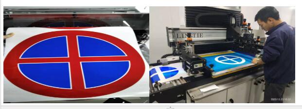
In order to meet the needs for on-site analysis, it is necessary that we transition away from traditional, commonly used cumbersome beakers and electrochemical cell systems. Nanotechnology and exploitation of new fabrication techniques offer simple, smaller, but robust sensing systems perfectly suited for on-site analyses. Screen-printing technologies take an important part as tool needed to take electrochemical biosensors towards point-of-care. Our screen printing machine is using the technology for heat transfer labels, RFID labels, biosensor labels, etc. Although it has been in existence for over a thousand years, screen-printing technology has only been exploited in biosensors in the last two decades.

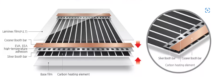
Screen-printing is one of the most promising approaches towards simple, rapid and economic production of biosensors. Disposable biosensors based on screen printed electrodes (SPEs) including microelectrodes and modified electrodes have led to new possibilities in the detection and quantization of bimolecular, pesticides, antigens, DNA, microorganisms and enzymes.
SPE-based sensors are in tune with the growing need for performing rapid and accurate in-situ analyses and for the development of portable devices.
Disposable screen-printed biosensors have been successfully employed in the development of analytical methods that respond to the growing need to perform rapid “in situ” analyses. Thus, the early detection of microorganisms, which plays an important role in the prevention of human health problems, animals and plants epidemics, has been carried out using this kind of devices. Moreover, microorganisms have been used as biological sensing elements in the development of sensitive microbial biosensors for the analysis of different analyses of interest.
Screen-printed disposable biosensors have been developed for the analysis of microorganisms such as Escherichia coli (E. coli), Salmonella, etc. In the same way, the incorporation of microorganisms in the SPE can be used for the analysis of different substances of analytical interest.
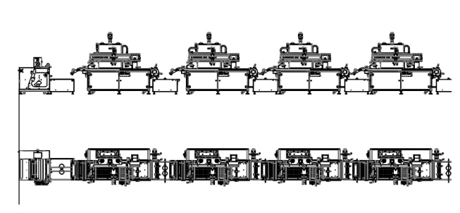
That is why we need to fully use of the screen-printing technology, which is a fast and cost-effective process, widely used in organic and printed electronics, and is one of the most promising technologies to produce electrochemical (bio)sensors for biomedical, agric-food and environmental applications . The advantages of screen-printed (bio)sensors include sensitivity, selectivity, possibility of mass-production and miniaturization, which facilitates the design of portable and cost effective measuring systems. Moreover, (bio)sensor fabrication through screen-printing technology is very versatile and this versatility is likely to underpin the progressive drive towards miniaturized, sensitive and portable devices, having already started to established its route from “lab-to-market” for a large number of sensors for both centralized and in-field analyses.