What are the main application industries of high and low temperature motors

High and low temperature motors are a specialized type of motor designed for stable operation in extreme temperature environments. They have special requirements regarding materials, lubrication, sealing, and manufacturing processes. They are widely used in various industrial and technological fields with demanding temperature requirements.

Here are the main industries where high and low temperature motors are applied:

I. Extreme Environments and Special Applications

Aerospace

Application Scenarios: Aircraft door actuation systems, engine starters, fuel pumps, environmental control systems (e.g., air conditioning compressors), robotic arms for space exploration equipment, Mars rovers.

Temperature Requirements: Must operate reliably in extremely low temperatures at high altitudes (-55°C or lower) as well as in high-temperature environments near engines.

Defense and Military

Application Scenarios: Drive and turret rotation systems for tanks and armored vehicles, missile rudder control, propulsion and auxiliary systems for naval vessels (especially submarines), field communication equipment.

Temperature Requirements: Must adapt to various global climatic conditions, from polar severe cold to desert heat, with extremely high reliability requirements.

Scientific Research and Laboratory Equipment

Application Scenarios: Environmental simulation test chambers (high/low temperature test chambers), moving parts within vacuum chambers, particle colliders, drive units for astronomical telescopes, polar research equipment.

Temperature Requirements: The experimental environment may range from ultra-low temperatures near absolute zero (-273°C) to high temperatures of several hundred degrees Celsius. Motors need to operate stably within these ranges without causing contamination (e.g., outgassing, volatilization).


II. Industrial Manufacturing and Process Control

Chemical and Oil & Gas Industry

Application Scenarios: Reactor agitators in refineries and chemical plants, pipeline valve control, liquefied natural gas (LNG) pumps, offshore drilling platforms.

Temperature Requirements: May be exposed to high-temperature steam, low-temperature cooling media, or be in flammable/explosive environments. Motors require explosion-proof and corrosion-resistant capabilities.

Food and Beverage Processing

Application Scenarios: Conveyor belt drives in freezing/cold storage facilities, agitators, filling equipment, high-temperature sterilization equipment.

Temperature Requirements: Must withstand low temperatures in cold storage (e.g., -40°C), and high-temperature steam and corrosive cleaning agents during washing and sterilization processes. Often must also comply with food-grade hygiene standards.

Plastics and Rubber Industry

Application Scenarios: Injection and mold clamping units of injection molding machines, drives for extruders.

Temperature Requirements: Motors are installed near high-temperature molds and need to withstand radiant heat and high ambient temperatures generated during equipment operation.


III. Civilian and Commercial Fields

New Energy Vehicles and Rail Transportation

Application Scenarios: Main drive motors for electric vehicles, air conditioning compressors, cooling water pumps; traction systems, door control, and air conditioning systems for high-speed rail and subways.

Temperature Requirements: Automotive motors must endure summer heat and winter cold, and themselves generate heat during operation, placing high demands on heat dissipation and cold-start performance. Rail transit motors also face outdoor climate challenges.

Medical Equipment

Application Scenarios: Medical centrifuges (e.g., blood separation), low-temperature refrigeration equipment, surgical robots, cooling systems in MRI (Magnetic Resonance Imaging) equipment.

Temperature Requirements: Some equipment needs to operate at ultra-low temperatures, while also requiring motors to run smoothly, with low noise and high precision.

Household Appliance Industry

Application Scenarios: Fans in high-end refrigerators, motors for rotating oven racks, drum drives for clothes dryers.

Temperature Requirements: Internal oven temperatures can reach 200-300°C, requiring motors capable of long-term heat resistance; freezer compartments in refrigerators require resistance to low temperatures.


Key Features of High and Low Temperature Motors

To adapt to these industries, high and low temperature motors typically possess the following characteristics:

Special Temperature-Resistant Materials: Use of high temperature-resistant insulation materials (e.g., Class H, C), high-temperature resistant permanent magnets (e.g., samarium-cobalt magnets), special sealing and lubrication materials.

Wide-Temperature Grease: Use of specialized grease that maintains good lubricating properties even at extreme temperatures.

Efficient Cooling/Heating Design: High-temperature motors focus on heat dissipation (e.g., adding cooling fans, water cooling jackets), while low-temperature motors may be equipped with heating belts to ensure cold starts.

Special Structural Design: Enhanced sealing to prevent condensation (low temperature) or harmful gases (high temperature) from intruding.


In summary, high and low temperature motors are the "core power" in numerous high-end equipment and special applications. They are essential wherever the operating environment temperature exceeds the range of standard motors (typically around -20°C to 40°C). Their application scope continues to expand with the development of technology and industry.

Extend Your Ice Storage Unit’s Lifespan by 5+ Years Essential Maintenance Tips

In the world of industrial equipment, ice storage units play a vital role. Their efficient operation not only ensures stable cooling for production and daily needs but also cuts costs for businesses. Proper maintenance is the key to extending their lifespan and keeping performance consistent—with the right care, your ice storage unit can last at least 5 years longer.


Daily Inspections: Don’t Overlook the Basics

Regularly check the unit’s exterior for damage and ensure all connections are tight. Loose screws should be tightened promptly to prevent component vibration from affecting stability. Also, inspect pipes for leaks: even minor drips, if ignored, can worsen over time, reducing cooling efficiency.

Hstars industrial cooling system ice storage Chiller


Cleaning: A Top Priority

Over time, dust and debris build up inside the unit, hindering heat dissipation and cooling performance. (Regularly clean) dirt from condenser and evaporator surfaces using professional cleaners—take care to avoid damaging components. Additionally, clean or replace air filters on schedule to ensure only clean air enters the unit, minimizing debris-related damage.
Electrical System Maintenance: Keep It Reliable
Check wires and cables regularly for damage or aging, and ensure all electrical connections are secure. Test control components like contactors and relays, replacing faulty ones promptly to prevent shutdowns or serious damage caused by electrical issues.

Lubrication: Reduce Wear and Tear

Follow the equipment manual to regularly add appropriate lubricants to moving parts like compressors and water pumps. Proper lubrication minimizes friction, reduces wear, and extends component life.

Maintaining an ice storage unit is a systematic process that requires attention to multiple areas. Through careful daily inspections, thorough cleaning, proper electrical upkeep, and timely lubrication, you can keep your unit in top condition. This not only extends its lifespan but also ensures reliable cooling, delivering long-term economic and social benefits.


Gachn Group's PP woven valve bag complete line solution one-stop turnkey service launched in West Africa

Amidst the rapid growth of the global packaging industry, PP woven valve bag products, thanks to their excellent performance, have found widespread application in numerous fields, including chemicals, building materials, and food.
For clients in emerging markets, building a complete and efficient PP woven valve bag production line and enabling localized packaging industry development is key to enhancing market competitiveness. Leveraging its strong technical expertise and extensive industry experience, Gachn Group successfully implemented a complete PP woven valve bag production line solution as a one-stop turnkey service at a client's factory in West Africa, injecting strong momentum into the local packaging industry.

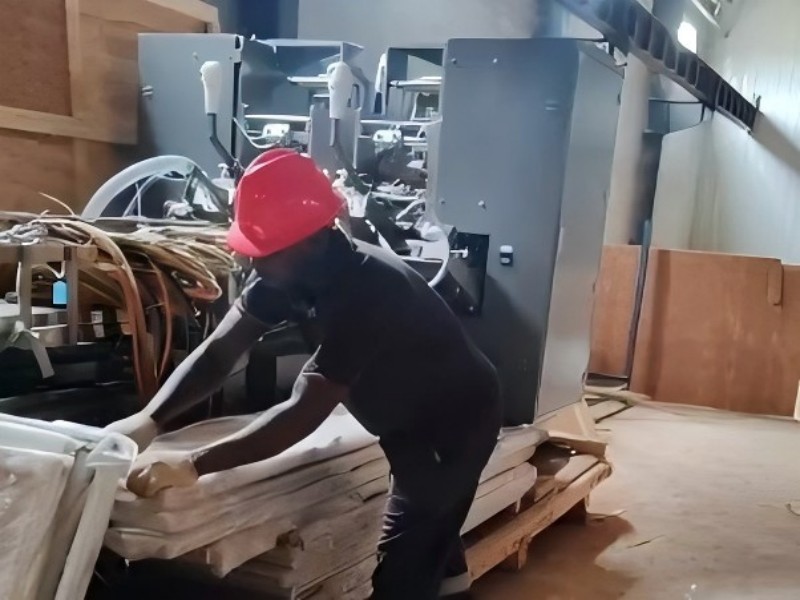
Bag making machine installation

Ⅰ. Turnkey Project: Worry-Free Project Guarantee

Gachn Group understands the complexities of overseas project implementation and has established a systematic, standardized turnkey project. From factory delivery to final acceptance, we strive for excellence in every step, providing customers with worry-free service.

Before equipment leaves the factory:Gachn Group conducts comprehensive and rigorous testing and commissioning of all equipment. Professional technicians, following a high-standard quality inspection system, meticulously inspect each piece of equipment for performance, accuracy, and safety, ensuring that each unit meets factory standards and lays a solid foundation for subsequent transportation and installation.

During transportation:Gachn Group collaborates with professional logistics partners to develop an optimal transportation plan based on the equipment's characteristics and road conditions at the destination. Customized packaging materials are used to properly package the equipment to protect it from impact, impact, and moisture during transportation. Transportation progress is monitored throughout the entire process, allowing for prompt response to any potential issues.

During the installation and commissioning phase:Gachn Group's after-sales team provides professional and high-quality service. They systematically install the equipment according to a detailed, pre-defined installation plan, ensuring precise positioning and secure connections. After installation, comprehensive commissioning is performed to optimize all equipment parameters for optimal operation.

During the pilot production phase:our after-sales engineering team will guide customers through small-batch production, verifying the equipment's operational performance and product quality through actual production. During the pilot production phase, potential issues are promptly identified and resolved, and production processes are adjusted and optimized to prepare for large-scale production.

During the final acceptance phase:Gachn Group and customers will conduct a comprehensive inspection of the equipment's performance, product quality, and production efficiency, based on pre-agreed acceptance criteria. Final acceptance is considered complete only when all indicators meet or exceed these standards.

Ⅱ. Technical Support: Strong Backing

Gachn Group's technical strength provides a strong backing for providing customers with high-quality solutions and services. This is due to the professional background and extensive experience of its engineers, as well as its continuous investment in technology research and development and services. Gachn Group boasts a R&D team of over 100 engineers, whose backgrounds span mechanical engineering, automation control, materials science, and other fields relevant to PP woven valve bag production. Their solid theoretical knowledge and extensive practical experience enable them to provide customers with professional technical support and solutions.

Gachn Group's engineering team has participated in numerous PP woven valve bag machine installation projects both domestically and internationally, accumulating extensive project implementation experience. They are also familiar with the principles of equipment installation.

Investment in technological R&D is key to Gachn Group's continued technological leadership. The company invests significantly annually in R&D, establishing a dedicated R&D team and advanced R&D laboratories. The R&D team continuously explores new technologies and processes, upgrades and improves equipment, and enhances performance and efficiency, while reducing energy consumption and production costs.

Regarding service investment, Gachn Group has established a comprehensive service system to provide comprehensive customer support. The company's dedicated service team provides timely and efficient after-sales service. Whether it's equipment installation and commissioning, troubleshooting, or routine maintenance, the service team responds to customer needs and resolves issues in the shortest possible time.

III. Industry Value: Supporting the Development of the Packaging Industry in Emerging Markets

Gachn Group's complete turnkey solutions are of great significance to overseas customers, particularly those in emerging markets, in developing localized packaging industries.

The packaging industry in emerging markets is often in its infancy, lacking comprehensive production systems and professional technical talent. Gachn Group's complete line solutions offer customers one-stop support, from equipment to service, helping them quickly build a complete PP woven valve bag production line, shortening project timelines and reducing project risks. Through localized production, clients in emerging markets can reduce their reliance on imported packaging, lower transportation and procurement costs, and improve product market responsiveness. Furthermore, localized production can drive the development of related local industries, create jobs, and boost economic growth.

Gachn Group's solutions can also help clients in emerging markets improve the quality and quality of their packaging products, enhance their market competitiveness, and promote the upgrading and development of the local packaging industry.

IV. Conclusion

If you are an overseas client, especially one in an emerging market, planning to develop a localized PP woven valve bag production line, Gachn Group's complete PP woven valve bag production line solution is an ideal choice. With strong technical capabilities, a comprehensive turnkey process, and a high-quality training system, we can provide you with worry-free service throughout the entire process.

Please contact us today to discuss your detailed proposal. Our professional team will provide personalized consultation and solutions to help your project succeed. Let us work together to create a bright future for the packaging industry!


PP Woven Valve Bag Extrusion line - Gachn, the Efficient and Intelligent Choice for Plastic Weaving Equipment

In the field of plastic woven machinery manufacturing, PP woven valve bags are widely used in the chemical, building materials, grain, and feed industries due to their high strength, excellent wear resistance, and strong sealing properties. In the upstream process of the valve bag production line, the wire drawing machine is a key piece of equipment that determines product quality and production efficiency.

Gachn Group's wire drawing machines are specifically designed for the production of high-quality PP flat yarn. Integrating intelligent, automated, energy-efficient, and environmentally friendly features, they are an ideal choice for many plastic weaving equipment manufacturers looking to increase production capacity and quality.


Why choose Gachn Group Extrusion line?

 
High-Precision Intelligent Control

1. Equipped with an imported intelligent PLC centralized control system, it supports synchronized speed adjustment across the entire line and individual machine fine-tuning, ensuring simple and stable operation.

2. PID temperature control ensures precise temperature control and more stable wire drawing quality.

 
Advanced Automation

1. The automatic belt screen changer supports mixing new PP materials with an appropriate amount of masterbatch, ensuring continuous screen change and significantly improving production efficiency.

2. The variable frequency drive system enables high-speed production, with a maximum winding speed of 450m/min.


High-quality finished yarn output

1. The extruder screw and barrel are made of 38CrMoALA high-strength alloy steel, which is wear-resistant and has a long service life.

2. The 4-roller drafting and 4-roller shaping combination achieves drafting speeds of up to 400m/min, producing uniform flat yarn with strong tension.


Energy-saving and environmentally friendly design

1. The total installed power is approximately 600kW, but the actual operating power is only 320-350kW, reducing energy costs.

2. Equipped with a side yarn crushing and recovery device, it reduces waste, ensuring environmental protection and high efficiency.


Gachn Group equipment parameters

Extruder Screw Diameter: Φ100mm-130mm

Length-to-Diameter Ratio (L/D): 33:1

Maximum Output: 650kg/h

Die Width: 1200-2100mm

Drafting Speed: 80-400m/min

Rewinding Speed: Up to 600m/min


Gachn Group PP Plastic Wire Drawing Machines Offer You Value

Improved Valve Bag Quality: High-strength PP flat yarn makes the woven fabric stronger and more durable.

Increased Productivity and Profit: High-speed production reduces costs and shortens payback period.

Adaptable to Diverse Production: Adjustable yarn width and thickness to meet the needs of valve bags of varying weights and applications.


Why Choose a Gachn Group Wire Drawing Machine?

Strong Stability: Full bridge-type wiring ensures clean and safe operation; the motor features overload and phase loss protection.

User-Friendly Maintenance: The equipment is rationally laid out, with ample maintenance space and a comprehensive spare parts supply.

International quality features: Siemens motors, Schneider electrical components, Nord reducers from Germany, and Fuji temperature control from Japan.


About Gachn Group - A Trusted Plastic Weaving Equipment Manufacturer

We have many years of experience in plastic woven machinery manufacturing, with a stable R&D team and comprehensive after-sales service. We provide customers with one-stop solutions, from equipment selection and installation and commissioning to technical training and parts supply.

If you are looking for a stable and cost-effective PP wire drawing machine, please contact us for a detailed quote and information to better understand our valve bag production line solutions.


Avoid Downtime, Cut Costs Smart Maintenance for Smarter Chillers

Screw water-cooled chillers typically operate around 3,000 hours per year, depending on China's climate and geographical conditions. Regular and scientific maintenance is crucial to ensure long-term, reliable operation, extend the lifespan, and reduce operating costs.

Hstars Screw refrigeration unit

Maintenance and Upkeep
Preventive maintenance during operation and inspection involves creating annual and monthly maintenance plans based on actual operating conditions.

Shutdown Procedures
In winter, clean and dry the unit. Open the drain valve to empty the shell-and-tube heat exchanger to avoid freezing. The shutdown sequence is: chiller off - cooling tower fan off - cooling water pump off - chilled water pump off. Special attention to anti-freezing:

1. Drain the evaporator and condenser if the unit is outdoors below 0°C during standby.
2. Interlock the water flow switch with the unit to prevent freezing when the chilled water flow switch malfunctions.
3. Ensure water in the evaporator is flowing or completely drained when charging or discharging refrigerant.


Concentration %

Freezing temperature ()

Concentration %

Freezing temperature ()

Concentration %

Freezing temperature ()

4.6

-2

19.8

-10

35

-21

8.4

-4

23.6

-13

38.8

-26

12.2

-5

27.4

-15

42.6

-29

16

-7

31.2

-17

46.4

-33


The concentration of ethylene glycol is a mass concentration.

Maintenance fault handling Smarter Chillers

Startup Procedures
After a long shutdown, prepare by thoroughly checking and cleaning the Screw refrigeration unit, cleaning the water pipeline system, inspecting the pump, tightening wiring connections, and preheating the compressor. The startup sequence is: cooling tower fan on - cooling water pump on - chilled water pump on - chiller on.


Refrigerant compressor water system Chiller


Common Fault Analysis and Troubleshooting

Fault

Possible Causes

Detection and Troubleshooting Methods

Excessive discharge pressure

Air or non-condensable gases in the system

Bleed gases via the refrigerant port and re-evacuate if needed

Cooling tower fan malfunction

Inspect and repair the fan to restore operation

Excessive suction pressure

See "Excessive suction pressure"

High ambient temperature

Insufficient cooling water flow

Check the cooling water system and increase the water flow.

Low compressor oil level

Check the oil level through the sight glass and add refrigeration oil

Low discharge pressure

Low suction pressure

See "Low suction pressure"

Refrigerant leakage or insufficient charge

Detect leaks and recharge refrigerant

Cooling water temperature too low

Check if the cooling tower capacity is excessively large or if the ambient temperature is too low

Excessive suction pressure

Discharge pressure too high

See "Discharge pressure too high"

Excessive refrigerant charge

Release part of the refrigerant

Liquid refrigerant flowing from the evaporator into the compressor

Chilled water inlet temperature exceeds maximum allowable value

Check and adjust the expansion valve, ensuring its temperature-sensing bulb is in tight contact with the suction pipe and fully insulated from the outside

Low suction pressure

Clogged filter drier

Replace the filter drier cartridge

Expansion valve improperly adjusted or malfunctioning

Adjust to the appropriate superheat temperature, or check if the expansion valve's temperature-sensing bulb is leaking

Insufficient refrigerant in the system

Detect leaks and recharge refrigerant

Chilled water inlet temperature significantly lower than specified value

Insufficient chilled water flow

Check if the pressure in the evaporator's inlet and outlet pipelines is too low, and adjust the chilled water flow rate

Compressor shutdown due to high-pressure protection

Cooling water temperature too high

Cooling tower fan malfunction

Overhaul the cooling tower fan

Incorrect high-pressure shutdown setting

Check the high-pressure switch

Compressor shutdown due to motor overload

Voltage too high or too low

Check that the voltage does not exceed or fall below the rated voltage by ±10%

Discharge pressure too high

Refer to "Discharge pressure too high"

Cooling water temperature too high

Check if the cooling tower capacity is too small

Overload component malfunction

Check the compressor current and compare it with the rated full-load current specified on the compressor

Motor or terminal short circuit

Check the corresponding resistance of the motor and terminals

Compressor shutdown due to built-in temperature protection switch activation

Voltage too high or too low

Check the voltage; it must not exceed the specified range mentioned above

Discharge pressure too high

See "Discharge pressure too high"

Chilled water inlet temperature too high

Compressor built-in temperature protection switch failure

Replace the component

Insufficient refrigerant in the system

Check for fluorine leakage

The compressor shuts down due to low-pressure protection

Drier filter blockage

Replace the drier filter element

Expansion valve failure

Adjust or replace the expansion valve

Incorrect low-pressure shutdown setting

Check the low-pressure switch

Insufficient refrigerant

Recharge the refrigerant

Loud compressor noise

Insufficient compressor refrigerating oil

Check the oil level in the sight glass and add refrigerating oil

The compressor fails to start

Overcurrent relay trips and fuse burns out

Replace the damaged components

Control circuit not connected

Check the wiring of the control system

No current

Check the power supply

High-pressure protection or low-pressure protection

See the section on suction and discharge pressure faults above

Contactor coil burned out

Replace the damaged component

Incorrect power phase sequence connection

Reconnect and swap any two wires

Water system failure, water flow switch open circuit

Check the water system

The operation display shows an alarm signal

Check the alarm type and take corresponding measures

Incorrect setting of start-stop time

Check and reset the settings

Temperature sensor detects temperature exceeding set value

Check and reset

From DX to Liquid Cooling The Race to a Greener Data Center

Data centers rely on diverse cooling methods, categorized into mechanical refrigeration and natural cooling. Mechanical systems include air-cooled direct expansion (DX), air-cooled chilled water, water-cooled chilled water, and centralized cooling water systems. Natural cooling encompasses fresh air, plate heat exchange, rotary heat exchange, evaporative cooling, and liquid cooling.

Data center cooling

Air-cooled DX Systems are traditional, with indoor units (compressor, evaporator) connected to outdoor condensers via refrigerant lines. Their simple design ensures reliability (no single point of failure). With fluoride pump energy saving (activating below 5°C), PUE in Zhejiang drops from ~1.71 to ~1.43.

Water-cooled Chilled Water Systems use centrifugal chillers and cooling towers, ideal for high heat loads. Winter free cooling via heat exchangers boosts efficiency (PUE ~1.43 in Zhejiang) but requires complex maintenance.


mechanical refrigeration natural cooling


Air-cooled Chilled Water Systems skip cooling towers, suiting moderate loads. They use air-cooled chillers and offer winter natural cooling, with a typical PUE of ~1.48 in Northeast China.

Liquid Cooling directly targets high-density servers, using water, mineral oil, or fluorinated fluids. Immersion cooling (e.g., fluorinated fluids) excels in efficiency, avoiding traditional HVAC limitations.


liquid cooling energy efficiency PUE optimization


Natural Cooling Technologies like fresh air (clean areas), plate exchangers (polluted environments), and evaporative cooling (dry climates) cut PUE by leveraging outdoor cold air, extending energy-saving periods.

Hstars liquid cooling energy efficiency PUE optimization

What Makes U-Shaped Stainless Steel Tubes the Key to Ice Storage Efficiency

Ice storage technology is a key energy-saving solution for modern buildings. By making ice during off-peak night hours (using lower electricity rates) and melting it for cooling during peak daytime, it significantly reduces air-conditioning operating costs. A critical component in this system? The U-shaped stainless steel heat exchanger tubes inside the storage tank—their design directly impacts efficiency, stability, and lifespan. Let’s break down this essential technology.


ice storage system chiller with thermal storage U-shaped heat exchanger tube


How Ice Storage Units Work & the Tank’s Role

An ice storage system consists of a refrigeration unit, ice storage tank, heat exchanger, and control system. Its core processes:

• Nighttime ice-making:

During low electricity demand, the refrigeration unit cools water or glycol in the tank below freezing, forming ice on the outer surface of heat exchanger tubes to store cold energy.


• Daytime ice-melting for cooling:

When demand peaks, hot return water is pumped into the tank. It exchanges heat with the ice, producing cold water for air conditioning.


The U-shaped stainless steel tubes play dual roles:

• In ice-making: They circulate refrigerants (like glycol) to transfer cold to the surrounding water.
• In ice-melting: They act as channels for cold water circulation, absorbing energy from melting ice.

Advantages of U-Shaped Stainless Steel Tubes

Compared to straight or coiled tubes, U-shaped stainless steel designs offer key benefits:

Efficient Heat Transfer & Uniform Ice Formation
• Larger contact area: The U-bend allows even tube distribution in limited space, boosting ice-making/melting efficiency.
• Reduced dead zones: Proper spacing avoids uneven ice buildup (common with straight tubes), ensuring uniform growth.

Freeze Expansion Resistance & Stress Relief

• Flexible structure: The U-bend absorbs stress from ice expansion via minor deformation, preventing cracks in low temperatures.
• Fewer welds: One-piece molding (one-piece construction) reduces leak risks from straight tube joints.

Corrosion Resistance & Longevity

• Stainless steel (304 or 316L) outperforms carbon steel in resisting chloride corrosion—ideal for long-term contact with water, glycol, and cold.
• Smooth surfaces minimize scale buildup, cutting maintenance needs.

Hstars anti-corrosion Heat Exchanger


Key Specifications & Selection Tips

• Material: 316L stainless steel suits high-chloride water (e.g., coastal areas) for better pitting resistance.
• Wall thickness: 0.8–1.5mm, based on pressure (atmospheric/pressurized systems) and freeze resistance.
• Design: DN15–DN25 diameters with spacing balancing efficiency and ice expansion room; U-bend radius ≥3x pipe diameter (to reduce flow resistance).
• Installation: Factory-assembled modular tube sets for on-site lifting; nylon/stainless steel brackets prevent vibration wear.
Real-World Case & Benefits
A commercial complex with an 800m³ tank (316L U-tubes, DN20, 1.2mm wall) achieved:


• 15% higher storage efficiency, 8-hour daytime cooling.
• Zero corrosion leaks over 10 years.

• Annual electricity savings of ~¥450,000, with a <4-year payback.


Future Trends

• Coatings: Anti-corrosion/nanoscale anti-scale coatings for longer life.
• Smart monitoring: Sensors tracking ice thickness and tube status to optimize storage.
• Lightweight design: Thin-walled high-strength stainless steel (e.g., duplex steel) reduces tank load.


U-shaped stainless steel heat exchanger tubes, with their efficiency, freeze resistance, and durability, are now the top choice for ice storage tanks. As materials and manufacturing advance, they’ll drive wider adoption in green buildings and district cooling—critical for carbon neutrality goals.


Analysis of the Relationship between Electric Motor Temperature Rise and Environmental Temperature

The relationship between the temperature rise, temperature, and ambient temperature of the electric motor can be clarified through the following analysis.

1.Basic Definitions

  • Ambient Temperature (Tamb)
    The temperature of the surrounding medium (typically air) where the motor operates, measured in °C or K.

  • Motor Temperature (Tmotor)
    The actual temperature of the motor's internal components (e.g., windings, core) during operation, measured in °C or K.

  • Temperature Rise (ΔT)
    The difference between the motor temperature and ambient temperature:ΔT=Tmotor−Tamb,Measured in K or °C (since temperature rise is a differential value, the units are interchangeable).

2. Mathematical Relationship

                                                        Tmotor=Tamb+ΔT

  • Temperature Rise () depends on:

    • Load Conditions: Higher load increases current and losses, leading to greater temperature rise.

    • Cooling Capacity: Heat dissipation design (e.g., fans, heat sinks) or environmental conditions (e.g., ventilation) affect ΔT.

    • Time: During startup or load changes, ΔT varies dynamically until reaching steady state.

3. Key Influencing Factors

  • Impact of Ambient Temperature:

    • If Tamb increases, the motor temperature Tmotor rises for the same ΔT.

    • High ambient temperatures may require derating the motor to prevent exceeding insulation limits.

  • Limits of Temperature Rise:

    • The motor's insulation class (e.g., Class B, F) defines the maximum allowable temperature (e.g., Class F = 155°C). Thus, the permissible ΔT must satisfy:ΔT≤Tmax−Tamb,where is the insulation material limit.

4. Practical Applications

  • Design Phase: The maximum ΔT is determined based on insulation class. For example, a Class F motor (Tmax=155°C) in a 40°C environment has an allowable of 155−40=115K (accounting for hotspot allowances).

  • Operation Monitoring: Abnormal temperature rise may indicate overloading, poor cooling, or insulation degradation.

  • Cooling Conditions: Changes in ambient temperature or cooling efficiency dynamically affect ΔT. For instance, fan failure causes a sharp rise in ΔT.

5. Summary of Relationships

  • Temperature rise (ΔT) results from the balance between power losses and cooling efficiency, independent of ambient temperature, but the actual motor temperature combines both.

  • Ambient temperature sets the baseline for cooling—higher Tamb reduces the allowable ΔT.

  • Motor temperature is the ultimate outcome and must comply with insulation limits.

Example

Consider a Class B insulation motor (Tmax=130°C) operating under two scenarios:

  • Ambient = 25°C, ΔT=80K: Tmotor=25+80=105°C (safe).

  • Ambient = 50°C, same ΔT=80K:Tmotor=50+80=130°C (at limit, requiring load reduction).

This relationship is fundamental to motor thermal protection design and lifespan evaluation.

How to Choose the Right Motor for Extreme Temperature Environments?

Choosing the right motor for extreme temperature environments requires careful consideration of several factors to ensure reliability, performance, and longevity. Here’s a step-by-step guide:

1. Define the Temperature Range

High Temperatures: Above 40°C (104°F) can degrade insulation, lubricants, and bearings.

Low Temperatures: Below -20°C (-4°F) can stiffen lubricants, embrittle materials, and reduce efficiency.

Fluctuating Temperatures: Thermal cycling can cause expansion/contraction stresses.

2. Select the Right Motor Type

AC Motors (Induction or Synchronous): Good for moderate extremes but may need modifications.

Brushless DC (BLDC) Motors: Better for wide temperature ranges due to electronic control.

Stepper Motors: Can work in extreme temps but may lose torque at very low temps.

Servo Motors: High precision but may need special encoders for extreme conditions.

3. Insulation Class (For High Heat)

Class B (130°C) – Standard for general purposes.

Class F (155°C) – Better for sustained high heat.

Class H (180°C) – Best for extreme heat (e.g., industrial ovens, aerospace).

Special High-Temp Motors: Some can withstand 200°C+ (e.g., ceramic-insulated windings).

4. Bearing & Lubrication Considerations

High-Temp: Use synthetic oils or dry lubricants (e.g., PTFE, silicone-based).

Low-Temp: Choose low-viscosity lubricants that don’t freeze (e.g., synthetic hydrocarbons).

Sealed Bearings: Prevent lubricant leakage in thermal cycling.

5. Material Selection

Housings: Stainless steel or aluminum with thermal coatings.

Magnets: Samarium-cobalt (SmCo) or neodymium (NdFeB) for high-temp resistance.

Seals & Gaskets: Viton or silicone for flexibility in extreme temps.

6. Thermal Management

Cooling Systems: For high temps, use forced air, liquid cooling, or heat sinks.

Heaters (For Cold): Prevents condensation and lubricant freezing.

Thermal Sensors: Built-in RTDs or thermistors for real-time monitoring.

7. Environmental Protection (IP Rating)

Dust & Moisture: IP65+ for harsh environments.

Explosion-Proof (ATEX/IECEx): Needed if flammable gases are present.

8. Power & Efficiency Adjustments

Derating: High temps reduce motor efficiency; may need oversizing.

Low-Temp Starting: Ensure sufficient torque at startup in cold conditions.

9. Supplier & Testing

Choose manufacturers with experience in extreme-temperature motors.Ctrl-Motor has been engaged in the R&D, production and sales of vacuum motors, high and low temperature motors-related drivers, stepper motors, servo motors, and reducers for 11 years. The high and low temperature motors can be adapted to any extreme conditions from -196℃ to 300℃, and the vacuum degree can reach 10-7pa, we can provide 10^7Gy radiation protection and salt spray protection products. 

Request test data (thermal cycling, cold start, endurance).

Final Tips

Consult Experts: Work with motor suppliers specializing in extreme environments.

Prototype Testing: Validate performance in simulated conditions before full deployment.

Maintenance Plan: Extreme conditions wear motors faster—schedule regular inspections.

By carefully evaluating these factors, you can select a motor that performs reliably in extreme temperatures. 

Material Selection for Servo Motors in Low-Temperature Environments

When using servo motors in low-temperature environments, material selection must carefully consider the effects of cold conditions on mechanical properties, lubrication performance, electrical insulation, and structural stability. Below are key material selection points and design recommendations:

1. Metal Structural Materials

Housing and Bearings:

Aluminum Alloy: Commonly used grades such as 6061 or 7075, subjected to T6 heat treatment to improve low-temperature toughness. Avoid ordinary cast iron (increased brittleness).

Stainless Steel: Grades like 304 or 316 offer low-temperature resistance and corrosion protection, suitable for extreme environments.

Bearing Steel: Use low-temperature-specific bearing steel (e.g., GCr15SiMn) or hybrid ceramic bearings (silicon nitride) to prevent reduced ductility in cold conditions.

Shaft Materials:

Maraging Steel (e.g., 18Ni300): High strength with excellent low-temperature toughness.

Low-Temperature Nickel Steel (e.g., 9% Ni Steel): Alternative for enhanced performance.

2. Lubricants

Low-Temperature Grease:

Base Oil: Polyalphaolefin (PAO) or ester-based oils with lithium complex or polyurea thickeners.

Recommended Products:

Mobilgrease 28 (-40°C to 150°C)

Klüber Isoflex Topas NB 52 (-60°C to 120°C)

Solid Lubricants: For ultra-low temperatures (<-60°C), consider molybdenum disulfide (MoS₂) or graphite coatings.

3. Electrical Components

Coil Insulation:

Magnet Wire: Polyimide (e.g., Kapton) or PTFE-coated wires; avoid PVC (becomes brittle at low temperatures).

Impregnation Resin: Modified epoxy or silicone resins (e.g., Dow Corning 1-2577).

PCB Substrates: High-Tg materials (e.g., FR-4 Tg≥170°C) or polyimide flexible circuits.

4. Seals and Elastomers

Seals:

Nitrile Rubber (NBR): Suitable above -40°C.

Fluorocarbon (FKM) or Silicone Rubber (e.g., modified EPDM): Required below -40°C.

Damping Components: Polyurethane (PU) or specialty silicone, with validation of low-temperature elasticity.

5. Other Critical Materials

Magnets:

Neodymium (NdFeB) magnets exhibit improved magnetic properties at low temperatures but require plating (e.g., Ni-Cu-Ni).

Samarium cobalt (SmCo) magnets for ultra-low temperatures.

Thermal Interface Materials: Low-temperature thermal grease (e.g., Bergquist SIL-Pad 2000) for motor-heatsink interfaces.

6. Design Validation

Material Testing: Conduct impact tests (e.g., Charpy), shrinkage rate, and insulation resistance measurements at target temperatures.

Assembly Tolerances: Account for differential thermal contraction (e.g., aluminum vs. steel CTE ratio ~2:1) via gaps or compensation structures.

Step Cooling Tests: Gradually reduce temperature while monitoring torque fluctuations, bearing resistance, etc.

Targeted material selection and rigorous validation ensure servo motors maintain precision, reliability, and longevity in low-temperature conditions. Practical applications should further optimize based on specific operational factors (e.g., cold-start frequency, load type).

Zhonggu Weike (Shenzhen) Power Technology Co., Ltd. is a National Specialized, Sophisticated, and Innovative ("Little Giant") enterprise specializing in the R&D, manufacturing, and application of special motors for harsh environments, including vacuum, high temperature, cryogenic, deep cryogenic, and radiation conditions. Its product range includes stepper motors, servo motors, radiation-resistant motors, vacuum modules, and vacuum gearboxes, among other standardized series.