Explain the working principle of magnetic pumps and the causes of demagnetization.

Magnetic pumps are commonly used pumps, and demagnetization is a relatively frequent cause of damage. Once demagnetization occurs, many people may find themselves at a loss, which could lead to significant losses in work and production. To prevent such situations, Anhui Shengshi Datang will briefly explain today why magnetic pumps experience demagnetization.


1. Magnetic Pump Structure and Principle

1.1 Overall Structure

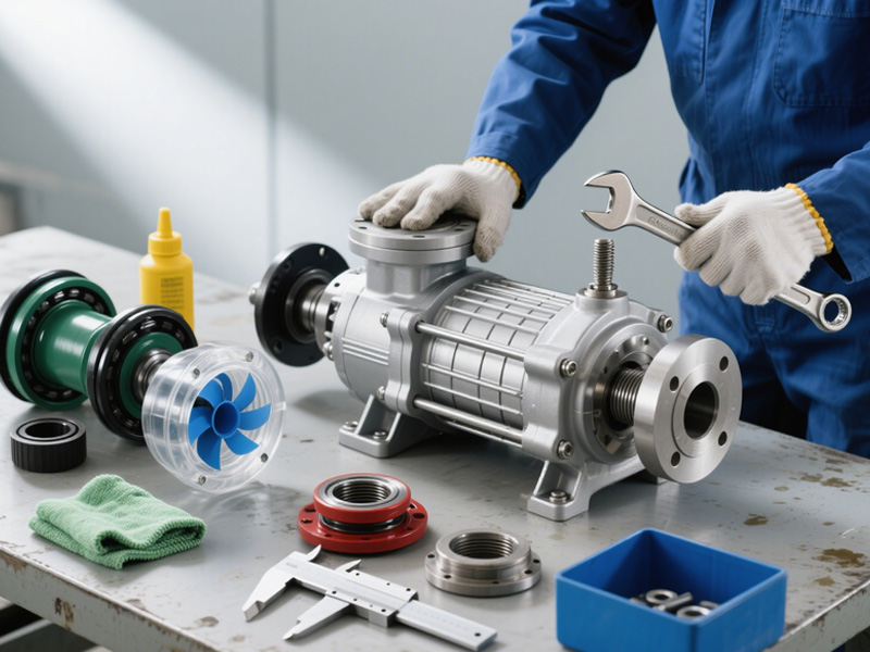
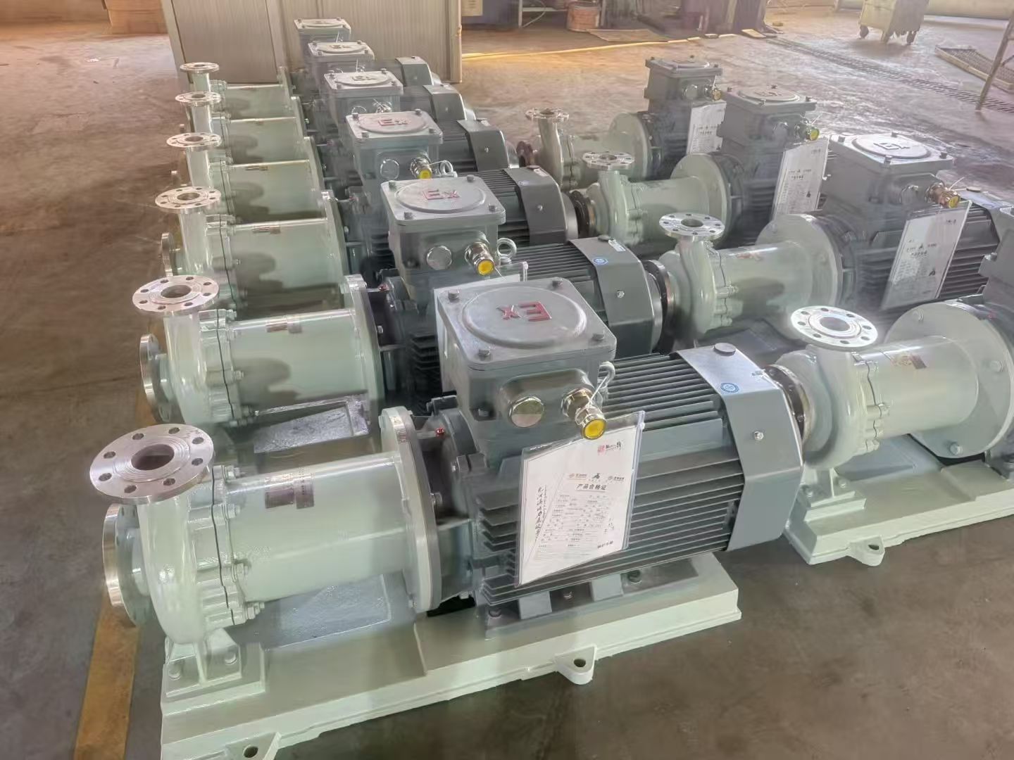
The main components of a magnetic pump's overall structure include the pump, the motor, and the magnetic coupler. Among these, the magnetic coupler is the key component, encompassing parts such as the containment shell (isolating can) and the inner and outer magnetic rotors. It significantly impacts the stability and reliability of the magnetic pump.


1.2 Working Principle

A magnetic pump, also known as a magnetically driven pump, operates primarily on the principle of modern magnetism, utilizing the attraction of magnets to ferrous materials or the magnetic force effects within magnetic cores. It integrates three technologies: manufacturing, materials, and transmission. When the motor is connected to the outer magnetic rotor and the coupling, the inner magnetic rotor is connected to the impeller, forming a sealed containment shell between the inner and outer rotors. This containment shell is firmly fixed to the pump cover, completely separating the inner and outer magnetic rotors, allowing the conveyed medium to be transmitted into the pump in a sealed manner without leakage. When the magnetic pump starts, the electric motor drives the outer magnetic rotor to rotate. This creates attraction and repulsion between the inner and outer magnetic rotors, driving the inner rotor to rotate along with the outer rotor, which in turn rotates the pump shaft, accomplishing the task of conveying the medium. Magnetic pumps not only completely solve the leakage problems associated with traditional pumps but also reduce the probability of accidents caused by the leakage of toxic, hazardous, flammable, or explosive media.


1.3 Characteristics of Magnetic Pumps

(1) The installation and disassembly processes are very simple. Components can be replaced anywhere at any time, and significant costs and manpower are not required for repair and maintenance. This effectively reduces the workload for relevant personnel and substantially lowers application costs.

(2) They adhere to strict standards in terms of materials and design, while requirements for technical processes in other aspects are relatively low.

(3) They provide overload protection during the conveyance of media.

(4) Since the drive shaft does not need to penetrate the pump casing, and the inner magnetic rotor is driven solely by the magnetic field, a completely sealed flow path is truly achieved.

(5) For containment shells made of non-metallic materials, the actual thickness is generally below about 8 mm. For metallic containment shells, the actual thickness is below about 5 mm. However, due to the thick inner wall, they will not be punctured or worn through during the operation of the magnetic pump.


2. Main Causes of Demagnetization in Magnetic Pumps

2.1 Operational Process Issues

Magnetic pumps represent relatively new technology and equipment, requiring high technical proficiency during application. After demagnetization occurs, operational and process aspects should first be investigated to rule out problems in these areas. The investigation content includes six parts:

(1) Check the magnetic pump's inlet and outlet pipelines to ensure there are no issues with the process flow.

(2) Check the filter device to ensure it is free of any debris.

(3) Perform priming and venting of the magnetic pump to ensure no excess air remains inside.

(4) Check the liquid level in the auxiliary feed tank to ensure it is within the normal range.

(5) Check the operator's actions to ensure no errors occurred during operation.

(6) Check the maintenance personnel's operations to ensure they complied with relevant standards during maintenance.


2.2 Design and Structural Issues

After thoroughly investigating the above six aspects, a comprehensive analysis of the magnetic pump's structure is necessary. The sliding bearings play a cooling role when the magnetic pump conveys the medium. Therefore, it is essential to ensure sufficient medium flow rate to effectively cool and lubricate the gap between the containment shell and the sliding bearings, and the friction between the thrust ring and the shaft. If there is only one return hole for the sliding bearings and the pump shaft is not interconnected with the return hole, the cooling and lubrication effect can be reduced. This prevents complete heat removal and hinders maintaining a good state of liquid friction. Ultimately, this can lead to seizure of the sliding bearings (bearing lock-up). During this process, the outer magnetic rotor continues to generate heat. If the inner magnetic rotor's temperature remains within the limit, the transmission efficiency decreases but can potentially be improved. However, if the temperature exceeds the limit, it cannot be remedied. Even if it cools down after shutdown, the reduced transmission efficiency cannot recover to its original state, eventually causing the magnetic properties of the inner rotor to gradually diminish, leading to demagnetization of the magnetic pump.


2.3 Medium Properties Issues

If the medium conveyed by the magnetic pump is volatile, it can vaporize when the internal temperature rises. However, both the inner magnetic rotor and the containment shell generate high temperatures during operation. The area between them also generates heat due to being in a vortex state, causing the internal temperature of the magnetic pump to rise sharply. If there are issues with the magnetic pump's structural design, affecting the cooling effect, then when the medium is delivered into the pump, it may vaporize due to the high temperature. This causes the medium to gradually turn into gas, severely affecting the pump's operation. Additionally, if the static pressure of the conveyed medium within the magnetic pump is too low, the vaporization temperature decreases, inducing cavitation. This can halt the medium conveyance, ultimately causing the magnetic pump bearings to burn out or seize due to dry friction. Although the pressure at the impeller varies during operation, centrifugal force effects can cause very low static pressure at the pump inlet. When the static pressure falls below the vapor pressure of the medium, cavitation occurs. When the magnetic pump contacts the cavitating medium, if the cavitation scale is small, it might not significantly affect the pump's operation or performance noticeably. However, if the medium's cavitation expands to a certain scale, a large number of vapor bubbles form inside the pump, potentially blocking the entire flow path. This stops the flow of medium inside the pump, leading to dry friction conditions due to the ceased flow. If the pump's structural design results in an inadequate cooling effect, the containment shell temperature can become excessively high and cause damage, subsequently increasing the temperature of both the medium and the inner magnetic rotor.

Prevention Measures for Centrifugal Pump Cavitation


In the previous section, we discussed the causes of centrifugal pump cavitation. Below, Anhui Shengshi Datang will introduce measures to prevent centrifugal pump cavitation.

1. Improvements in Design and Materials

From the perspectives of design and materials, the following measures can be taken to prevent or mitigate the hazards of centrifugal pump cavitation:

A. Gap Optimization Design: Appropriately increase the clearance between moving parts, especially between the impeller and the pump casing, and between the seal ring and the shaft, to reduce the risk of seizing due to thermal expansion. Research shows that increasing the standard clearance by 15%-20% can significantly reduce the probability of seizing during cavitation, with minimal impact on pump efficiency.

B. Material Selection and Treatment:

  a. Perform tempering heat treatment on the pump shaft to improve its hardness and wear resistance, reducing deformation and wear during cavitation.

  b. Select materials with low thermal expansion coefficients, such as stainless steel or special alloys, to minimize clearance changes caused by thermal expansion.

  c. Apply wear-resistant coatings like hard alloy or use ceramic materials for key friction parts such as seal rings to enhance wear resistance.

C. Sealing System Improvements:

  a. Use mechanical seals that do not rely on the pumped medium for lubrication, such as gas-lubricated mechanical seals or double mechanical seals.

 b. Configure external lubrication systems to provide lubrication for the seal faces even when the pump is cavitating.

 c. For packing seals, use self-lubricating packing, such as composite packing containing PTFE.


D. Bearing System Optimization:

 a. Use enclosed self-lubricating bearings to reduce dependence on external cooling.

 b. Add independent cooling systems for bearings to ensure normal bearing temperature is maintained even during pump cavitation.

 c. Select bearings and lubricants with higher temperature tolerance.

E. Pump Cavity Design Improvements:

 a. For special applications, design a water storage space so that the pump can maintain a minimum liquid volume even during short-term water shortage.

 b. Self-priming pumps are typically designed with a larger pump cavity volume and specialized gas-liquid separation devices, allowing them to better handle short-term cavitation.

Practice shows that reasonable design and material selection can reduce the risk of damage during centrifugal pump cavitation by over 50%, while also extending the overall service life of the equipment.

2. Application of Monitoring and Control Systems

Modern monitoring and control technologies provide effective means to prevent centrifugal pump cavitation:

A. Cavitation Detection Systems:

 a. Flow Monitoring: Install a flow meter at the pump outlet to automatically alarm or shut down the pump when the flow rate falls below a set value.

 b. Current Monitoring: Motor load decreases during cavitation, leading to a significant drop in current; cavitation can be detected by monitoring current changes.

 c. Pressure Monitoring: A sudden drop or increased fluctuation in outlet pressure is a key indicator of cavitation.

 d. Temperature Monitoring: Abnormal temperature rises in mechanical seals, bearings, or the pump body can indirectly reflect the cavitation state.

B. Liquid Level Control Systems:

 a. Install level sensors in water tanks, sumps, and other intake facilities to automatically stop the pump when the level falls below a safe value.

 b. For special occasions, set up dual-level protection: low-level alarm and very low-level forced pump shutdown.

 c. Use non-contact level gauges (e.g., ultrasonic, radar) to avoid potential jamming issues associated with traditional float switches.

C. Integrated Intelligent Control Systems:

 a. Integrate multiple parameters (flow, pressure, temperature, level) into a PLC or DCS system to more accurately identify cavitation status through logical judgment.

 b. Set up two levels of protection: cavitation warning and cavitation alarm. The system can attempt to automatically adjust operating conditions during a warning and force a shutdown during an alarm.

 c. Use expert systems or artificial intelligence technology to predict potential cavitation risks in advance through historical data analysis.

D. Remote Monitoring and Management:

 a. Utilize IoT technology to achieve remote monitoring of pump stations, enabling timely detection of abnormalities.

 b. Establish fault prediction models to provide early warnings of potential cavitation risks through big data analysis.

 c. Set up automatic recording and reporting systems to log changes in operating parameters, providing a basis for fault analysis.

Data shows that centrifugal pumps equipped with modern monitoring and control systems experience over 85% fewer cavitation incidents compared to traditional equipment, with significantly reduced maintenance costs. The value of these systems is particularly evident in unattended pump stations.


3. Operating Procedures and Maintenance Management

Scientific operating procedures and maintenance management are crucial links in preventing centrifugal pump cavitation:

A. Pre-Startup Checks and Preparation:

 a. Confirm that valves on the suction line are fully open and filters are not clogged.

 b. Check the sealing of the pump casing and pipelines to ensure there are no air leakage points.

 c. Ensure the pump is fully primed and air is completely vented before the first startup or after a prolonged shutdown.

 d. Manually rotate the pump shaft several turns to ensure it rotates flexibly without abnormal resistance.

B. Correct Startup and Shutdown Procedures:

 a. Open the suction valve first, then the discharge valve, avoiding starting against a closed discharge valve.

 b. For large pumps, start with the discharge valve slightly open, then fully open it once operation stabilizes.

 c. When stopping the pump, close the discharge valve first, then the motor, and finally the suction valve to prevent backflow and water hammer.

 d. Drain liquid from the pump casing promptly after shutdown in cold winter regions to prevent freezing.

C. Monitoring and Management During Operation:

 a. Establish an operating log system to regularly record parameters such as flow, pressure, temperature, and current.

 b. Implement an inspection round system to promptly detect abnormal noise, vibration, or leaks.

 c. Avoid prolonged operation at low flow rates; install a minimum flow bypass line if necessary.

 d. For multi-pump parallel systems, ensure reasonable load distribution among pumps to avoid single pump overload or cavitation.

D. Regular Maintenance and Inspection:

 a. Regularly clean suction line filters to prevent clogging.

 b. Check the condition of mechanical seals or packing seals, and replace aged or damaged parts promptly.

 c. Regularly check bearing temperature and lubrication status, adding or replacing lubricant as required.

 d. Periodically measure seal ring clearances to ensure they are within allowable limits.

 e. Check that balance pipes and balance holes are clear (applicable to multi-stage pumps).

E. Personnel Training and Management:

 a. Provide professional training for operators and maintenance personnel to improve their ability to identify and handle faults.

 b. Formulate clear responsibility systems and emergency plans to ensure a rapid response in case of abnormalities.

 c. Establish experience sharing mechanisms to promptly summarize and disseminate fault handling experiences.

Practice proves that sound operating procedures and maintenance management can reduce unplanned downtime of centrifugal pumps by over 70%, significantly improving equipment reliability and service life.


4. Response Measures for Emergency Situations

Despite various preventive measures, centrifugal pump cavitation may still occur under special circumstances. In such cases, emergency response measures are needed to minimize losses:

A. Rapid Identification and Shutdown:

 a. If signs of cavitation such as abnormal noise, increased vibration, or a sudden drop in discharge pressure are detected, the pump should be shut down immediately for inspection.

 b. For critical equipment, emergency stop buttons can be installed to halt the pump immediately upon detecting abnormalities.

 c. Do not repeatedly start the pump before confirming and eliminating the cause of cavitation, to avoid exacerbating damage.

B. Emergency Cooling Measures:

 a. If the pump body is found to be overheated but serious damage has not yet occurred, external cooling measures can be taken, such as wrapping the pump body with wet cloths or applying slight water spray cooling (taking care to avoid electrical components).

 b. Do not immediately cool overheated bearings with cold water, to prevent damage from thermal stress.

C. Restoring Normal Liquid Supply:

 a. Check and clear blockages in the inlet pipeline.

 b. For insufficient liquid level, promptly replenish the water source or lower the pump's installation height.

 c. Check and repair air leakage points in the pipeline system.

D. Special Monitoring After Restart:

 a. When restarting the pump after a cavitation event, pay special attention to whether the seal is leaking, if the bearing temperature is normal, and if vibration is within allowable limits.

 b. Only resume normal operation after confirming all parameters are normal.

 c. It is recommended to increase the frequency of inspection rounds temporarily to ensure stable equipment operation.

E. Damage Assessment and Repair:

 a. Pumps that have experienced severe cavitation should undergo a comprehensive inspection to assess the extent of damage.

 b. Replace damaged components if necessary, such as mechanical seals, seal rings, and bearings.

 c. Inspect the impeller and pump casing for damage caused by cavitation.

Through timely and effective emergency handling, losses caused by cavitation can be minimized. Statistics show that reasonable emergency measures can reduce equipment recovery time by over 50% in emergency situations, while also reducing the risk of secondary damage.

Daily maintenance of horizontal baling machine

The horizontal baler stands as a cornerstone equipment within the waste management and recycling sector. Its work principle involves using hydraulic power to compress materials. When materials are fed into the baler, a hydraulic cylinder exerts immense pressure, gradually squeezing the materials together. As the pressure builds up, the materials are compacted into tightly packed bales.


Engineered to compress an array of materials, including cardboard, paper, plastics, and even metals, into tightly packed bales, it dramatically diminishes waste volume. This reduction enhances the efficiency and cost-effectiveness of both storage and transportation processes.


A primary benefit of horizontal balers lies in their remarkable versatility. They are capable of processing a diverse spectrum of materials, effortlessly adjusting to varying sizes and shapes. This adaptability renders them suitable for a multitude of industries, spanning from manufacturing to retail operations.


Furthermore, horizontal balers are renowned for their impressive compression ratios, guaranteeing that the bales they produce are both dense and stable. This not only conserves valuable space but also significantly reduces the likelihood of bales disintegrating during handling and transportation.


After each day's work is completed, it's the best time for maintenance:


Thorough Cleaning:

Remove any remaining paper scraps and debris from the hopper.

Clean dust and oil from the pusher head, compression chamber, and bale outlet.

Clean the equipment surface, keeping it clean overall.


Inspect Key Components:


Blades and Seals:

Check the sealing strips on the compression chamber door for damage. Replace any damaged strips immediately to prevent leakage. Check the sharpness of the cutter.


Chain/Wire Rope:

 For equipment using chains or wire ropes for threading, check their wear and tension, and add appropriate amounts of lubricating oil.


Lubrication:

Add the specified grease or lubricating oil to all lubrication points (such as guide rails, sliders, bearing housings, etc.) according to the equipment manual.


Hydraulic System:

After shutting down, check again for any leaks.

Clean the area around the oil tank filler neck to prevent impurities from entering.


In essence, the horizontal baler assumes a critical role in contemporary waste management strategies. Its efficiency, adaptability, and superior compression abilities render it an indispensable tool for businesses seeking to optimize their waste disposal and recycling workflows.

Daily maintenance of metal balers

Metal balers are essential equipment in the metal recycling and processing industries. Their maintenance is directly related to their service life, cutting efficiency, and production safety.


Daily Maintenance (Before and After Each Shift)

This is the most basic and crucial maintenance, performed by the operator.


1. Pre-Startup Inspection:

Lubrication Check: Check all lubrication points (such as the master cylinder, door hinges, and slide rails) for sufficient lubricant/grease.


Hydraulic System Check: Check that the hydraulic oil level is within the specified range and inspect the oil tank, oil lines, and joints for leaks.


Electrical System Check: Check for damaged or loose wiring and that the emergency stop button is functioning.


Fasteners Check: Quickly check for loose bolts and nuts in critical locations.


Cleaning the Material Bin: Ensure that the baling chamber is free of debris or debris from the previous shift, especially metal that could prevent the door from closing.


2. Observation During Operation:

Abnormal Noise and Vibration: Pay attention to any unusual noise or excessive vibration during operation.


Oil Temperature Monitoring: Observe whether the hydraulic oil temperature rises abnormally (usually should not exceed 60-70°C).


Operation Smoothness: Observe whether each cylinder operates smoothly and whether there is any creeping.


Pressure Gauge Reading: Note whether the system operating pressure is normal and whether there are any excessive fluctuations.


3. Post-Shutdown Maintenance:

Thorough Cleaning: Clean dust, oil, and metal debris from the equipment surface. Focus on cleaning the packaging chamber, pusher head, and door cover seal contact surfaces.


Draining: If the system is air-cooled, check and drain condensate from the air filter.

Metal Shredder Buying Guide

Understanding the Core Components of a Metal Shredder


A metal shredder is more than just a machine; it's a system. Here are its core components:


1. Main Unit:


Cutter Shaft: Single, dual, or quadruple shaft? Dual shafts are most common, processing metal by shearing and tearing.


Blades:Material (usually alloy steel), shape, number, and repairability. Blades are consumable parts, so their quality and durability are crucial.


Housing: Heavy-duty steel structure ensuring stable operation under high loads.


Power System:Typically an electric motor (electric) or diesel engine (for mobile or non-electric areas).


2. Feeding System:


Conveyor:Belt conveyor or chain conveyor for automatic, uniform feeding.


Feeding Method: Manual feeding, conveyor feeding, or steel grabber feeding.


3. Discharge System:


Conveyor: Transports the shredded material away.


Magnetic Separator (Optional but Important):Used to separate metallic and non-metallic impurities.


Dust Collection System (Environmental Requirements): Collects dust generated during the shredding process, meeting environmental standards.


4. Control System:


PLC Control: High degree of automation, capable of monitoring load, setting automatic reverse (anti-jamming), and fault alarms.


Electrical Cabinet: Core control unit.

Routine maintenance of container shears


Container shears are heavy-duty industrial equipment primarily used to compress and shear various metal scraps (such as steel sections, plates, auto bodies, and lightweight materials) into high-density "blocks" for easier transportation, storage, and improved smelting efficiency.

Before starting work each day, the following checks must be performed:


1. Cleaning and Visual Inspection


Remove debris: Remove dust, oil, metal shavings, and other debris from the equipment surface, around the blades, and the feed chute. Keeping the equipment clean prevents debris from affecting cutting accuracy and damaging the equipment.


Visual Inspection: Visually inspect all parts of the equipment for obvious damage, cracks, or deformation.


2. Lubrication Check


Check Oil Level: Check that the hydraulic oil level in the hydraulic system is within the range specified on the oil level gauge. If the oil level is too low, add hydraulic oil of the same grade immediately.


Check Lubrication Points: Add an appropriate amount of grease or lubricating oil to all lubrication points specified in the equipment manual (such as slide rails, bearing seats, pins, etc.). Ensure that moving parts are well lubricated.


3. Fastener Inspection


Check Critical Bolts: Focus on checking the tightness of critical parts such as anchor bolts, blade fixing bolts, and hydraulic line joints to ensure there is no looseness. Looseness can lead to increased vibration, increased noise, and even accidents.


4. Electrical System Inspection


Inspect Wiring: Visually inspect cables and wires for damage, aging, or exposed wires.


Inspect Operating Buttons: Test the sensitivity and reliability of all operating buttons (such as start, stop, up, down). The emergency stop button must function effectively.


5. Blade Inspection


Inspect Blade Edges: Check the sharpness of the upper and lower blades, ensuring there are no chips, curled edges, or severe wear. Dull blades will reduce shearing quality and increase equipment load.


6. No-Load Trial Run


Before starting formal work, start the equipment and perform several no-load shearing cycles. Listen to the equipment's operating sound to ensure it is normal, and observe the hydraulic system for any abnormal vibrations or leaks. Work can only begin after confirming everything is normal.

What Makes the HGP-Digital UV Inkjet Printing Machine the Best Choice for High-Volume Custom Printing?

In today’s fast-moving print and packaging industries, choosing the right machine can make or break productivity and cost efficiency. The HGP-Digital UV Inkjet Printing Machine is designed for companies seeking high precision, broad substrate compatibility, and low downtime. From signage and custom packaging to industrial components, it supports a wide range of materials and workflows.


This article explores why the HGP system stands out, what features matter most, and how to assess whether it fits your production environment.

The High-Speed 9 Color UV Printer is designed for industrial-grade, single-pass UV inkjet printing

1. Market & Industry Context

The global UV inkjet printing market continues to expand rapidly — projected to grow from USD 54.85 billion in 2024 to USD 60.61 billion in 2025, reflecting an estimated CAGR of around 9.6%.
The growth is driven by customization demands, eco-friendly printing needs, and the shift toward digital high-speed production.

Year Market Size (USD bn)
2024 54.85
2025 60.61
2030 ~86.05


These figures highlight strong momentum in UV inkjet technology. For equipment buyers, it signals that now is the time to invest — early adopters of systems like the HGP series can gain a clear competitive advantage in both cost efficiency and production flexibility.


2. Core Features of the Machine

Let’s explore three essential feature sets that make this printer a market leader — while naturally embedding high-value long-tail search keywords.


(1) Versatility: HGP-Digital UV Inkjet Printer for Multiple Substrates

Unlike traditional printers limited to one medium, the HGP model is engineered for both rigid and flexible materials. It prints directly on acrylic, metal, wood, plastic, and vinyl — all with outstanding color fidelity.

This makes it an excellent UV Printer for Signage and Packaging, ideal for manufacturers who need to switch quickly between large-format boards, corrugated boxes, or plastic sheets without tool changes.


(2) Productivity: High-Speed Performance for Volume Printing

Speed and accuracy define profitability in today’s market. The HGP-Digital UV Inkjet Printing Machine achieves production rates up to 50 m/min, depending on resolution and substrate type.

Its High-volume UV Inkjet for Fast Printing capability allows shorter lead times, instant ink curing, and reduced bottlenecks. Compared to conventional solvent systems, users typically see 30–40% faster turnaround with significantly lower drying time.

That efficiency translates to higher output with the same footprint — ideal for contract manufacturers or private-label printers.


(3) Sustainability: Low Power, Low Emission Curing

Modern printing requires environmental responsibility. The HGP machine adopts UV-LED curing technology, dramatically cutting both VOC emissions and energy use.

As a Low Energy UV-LED Inkjet Printer, it consumes up to 50% less power than mercury-lamp systems while maintaining equal or better curing strength.

This means cleaner air, less heat stress on substrates, and reduced maintenance costs — a win for both operators and the planet.


3. Material Compatibility & Application Range

One of the strongest advantages of the HGP-Digital UV Inkjet Printer is its wide substrate compatibility.

Users can print directly on:

  • Glass, acrylic, aluminum composite, wood, and plastic

  • Flexible films, banners, or soft PVC

  • Industrial parts requiring direct marking or variable data

Substrate Typical Application Curing Performance
Acrylic / Metal Panels Indoor signage & displays Instant, no color bleed
Film / Vinyl Banners Outdoor wraps Flexible, UV-LED cure
Wood / MDF Panels Furniture, décor panels Low heat stress
Plastic (ABS, PETG) Custom enclosures Non-absorbent surfaces


This multi-material flexibility enables a single system to replace multiple dedicated printers — a key reason why so many users transition to the HGP platform.


4. ROI & Productivity Metrics

Evaluating return on investment is crucial before any equipment purchase.

Below are sample operational benchmarks observed in industrial use cases:

Parameter Typical Value / Benefit
Print speed Up to 50 m/min
Ink cost per m² ~20% lower vs solvent printing
Substrate changeover Under 10 minutes
Energy savings 40–50% less than conventional UV systems
Maintenance downtime Reduced by 30% through automated cleaning


When factoring in consumable savings, reduced downtime, and faster production cycles, many businesses achieve ROI in 24–36 months.


5. Setup & Operational Best Practices

To ensure consistent print quality and machine longevity, operators should consider:

  • Substrate flatness: Prevent nozzle misfires and registration drift.

  • Ink compatibility: Use only UV-LED-certified inks for adhesion and gloss control.

  • Ambient environment: Maintain stable humidity and airflow for optimal curing.

  • Maintenance routine: Regular head cleaning prevents clogging and improves color uniformity.

  • Workflow alignment: Integrate RIP software and material handling for continuous production.


Proper setup and training can improve throughput by 15–20% on average.


6. Why the HGP-Digital UV Inkjet Printing Machine Stands Out

While other UV printers compete on either speed or versatility, the HGP model combines both.

It provides:

  • True hybrid printing (rigid + flexible substrates) on one platform

  • High-precision color reproduction through intelligent RIP processing

  • Expandable architecture for white ink, varnish, or variable data options

  • Low maintenance and modular upgrades, ideal for small to mid-sized enterprises scaling up


Its balance of speed, sustainability, and scalability makes it a future-ready investment for companies expanding into custom digital printing.


The Eyes and Brain of Intelligence A Deep Dive into the Intelligent Control System of the Gachn Truck Loader

A superior automated truck loader relies on a robust mechanical structure as its "limbs," but its true soul lies in its "eyes" and "brain." This week, we'll delve into the core, revealing how the Gachn truck loader achieves highly intelligent, unmanned loading through the seamless collaboration of 3D vision, AI algorithms, and advanced control.

In the past two weeks, we discussed industry pain points and introduced the revolutionary "cargo box entry" mechanical solution. However, for the robotic arm to precisely extend into the truck bed and perfectly stack the loads, an intelligent system for perception, decision-making, and execution is indispensable. This is precisely what distinguishes Gachn from simply cobbled-together automated equipment on the market, making it a truly "intelligent truck loader."


I. Intelligent Eyes: All-Aspect Perception for Clear Vehicle Identification

Core Technology: LiDAR 3D Scanning and Intelligent Vehicle Position Recognition System

Challenges: Vast Variations in Vehicle Parking: Improper parking, centerline deviation, and foreign objects in the cargo compartment (such as residual binding ropes or debris) can all lead to loading failures or even equipment collisions.


Our Solution:

Precise Modeling: The equipment uses high-precision LiDAR to perform an all-around scan of the parked vehicle, generating a 3D point cloud model with millimeter-level precision. This system automatically measures the length, width, and side panel height of the cargo compartment, as well as the vehicle's ground clearance.

Intelligent Judgment: Utilizing a self-developed intelligent detection algorithm, the system analyzes the point cloud data in real time. It automatically identifies whether the vehicle is parked within the permitted automated loading area and whether the centerline deviation is within a controllable range. Simultaneously, it acts as a "quality inspector," detecting any irregularities in the cargo compartment to prevent unstable stacking or equipment malfunctions caused by foreign objects.

Active Guidance: If the system detects that the rear panel is too high or the parking position is improper, it will proactively remind the driver via screen to "open the rear panel" or "adjust the parking position," achieving human-machine interaction and ensuring a perfect starting point for the operation.


(Video: Showing the 3D point cloud model of the vehicle generated after LiDAR scanning, with the measured length, width, and height dimensions marked)


II. Intelligent Brain: Strategic Planning for Optimal Loading Path

Core Technology: Proprietary Palletizing Algorithm and Schneider Electric High-End Control Platform

Challenge: How to convert known vehicle dimensions and the tonnage to be loaded into precise, neat, and stable palletizing coordinates and movement trajectories for each bag of cement?

Our Solution: Intelligent Calculation: After acquiring 3D scan data, our independently developed palletizing logic algorithm begins operation. Based on the tonnage of cement to be loaded and a mathematical model, it automatically calculates the optimal landing coordinates for each bag of cement and plans the most efficient, collision-free movement trajectory.

Flexible Strategy: The algorithm supports three modes: horizontal stacking, vertical stacking, and a combination of both. It can intelligently select or combine modes based on the truck bed dimensions, ensuring tight and neat stacking, maximizing truck bed space utilization, and facilitating unloading.

Precise Execution: The calculated trajectory instructions are received and executed by a control system centered on a high-performance Schneider 12-axis motion controller and a 15.6-inch large touchscreen. The stability and high processing power of the Schneider PLC ensure the synchronization, accuracy, and reliability of the actions of all servo motors, cylinders, and other actuators.

Cement loading flowchart


III. Neural Networks: Data Interconnection, Enabling Intelligent Factory Management

Core Technology: Loading Information Management System and Industrial-Grade Interface

Challenge: The automated loading machine should not be an information silo; it needs to seamlessly integrate with the factory's existing management system.

Our Solution: The driver only needs to swipe their card next to the loading machine, and the system automatically retrieves the pickup information (such as customer, product type, and tonnage) from the ERP system, eliminating the need for manual input and preventing errors.

After loading is completed, data (such as actual loading time and tonnage) is automatically transmitted back to the management system, forming a closed loop and providing real-time and accurate data support for financial settlement and production scheduling.

The equipment is equipped with an Ethernet interface as standard, reserving ample expansion space for the factory's future Industry 4.0 and smart manufacturing upgrades.


IV. Reliable Foundation: Distributed Layout and Top-Tier Components

We understand that even the most intelligent system requires stable hardware support. Unlike competitors who centralize subcontracting, steering, and packing mechanisms, resulting in "small maintenance space and difficult fault handling," Gachn adopts a distributed layout. This layout not only offers higher stability but also provides spacious maintenance access when maintenance is needed, allowing for rapid problem location and resolution, significantly reducing downtime and improving overall equipment efficiency (OEE).

Conclusion: True intelligence is the perfect integration of perception, decision-making, execution, and management. The Gachn loading machine is precisely such an intelligent loading expert with "eagle eyes," a "super brain," and "flexible limbs." It brings not only savings in manpower, but also a comprehensive leap in loading quality, management efficiency, and data transparency.


How to Choose Forged Wheels That Perfectly Fit Your Car?

Choosing the right forged wheels isn’t just about style—it’s about matching your car’s specs, performance needs, and driving habits. With options like T6061-T6  one piece forged wheels and two piece forged wheels,even three piece forged wheel. It’s easy to feel stuck. But breaking down key factors helps you find wheels that look great and boost safety and performance. Let’s walk through the essential steps to get the perfect fit.


First, check your car’s basic specs. Every vehicle has strict requirements for wheel size, bolt pattern, offset, and load capacity—ignoring these causes poor fitment, damage, or safety risks. For a compact SUV, 20 inch wheels with a 6x139.7 bolt pattern mean 20 inch 6 holes forged wheels could be ideal. Find details like diameter (20inch), width (7J/8J), bolt pattern (holes x distance), offset (ET value), and load capacity in your owner’s manual or online. These numbers are non-negotiable—your wheels must match them.

3D drawing for forged wheel

                                                                     3D design for customer double check the required size

Next, align with your driving style. Daily commuters prioritizing comfort? T6061-T6 forged wheels balance strength, lightness, and affordability—their heat-treated alloy resists bending, perfect for daily drives. Racing or high-performance fans? one-piece forged wheels are lighter and stiffer, cutting unsprung weight for better acceleration, braking, and cornering. Want custom style with easy upkeep? Two-piece forged wheels offer design flexibility without losing much performance.


Don’t skimp on material and quality. Cheap knockoffs lack the strength of genuine forged wheels. Stick to reputable brands using 6061 aluminum alloy. Perfect aluminum alloy forged wheels from trusted suppliers save money for bulk buys, but verify manufacturing—look for rotary forging (uniform grain = more strength) and certifications like JWL/VIA. A well-made forged wheel lasts years, even in harsh conditions—quality now saves money later.


Aesthetics matter, but function first. Forged wheels come in sleek minimalist or bold intricate designs. Luxury sedans shine with polished/powder-coated wheels with clean lines; off-road trucks need larger, rugged wheels for bigger tires and traction. Complex designs are harder to clean—simpler styles are easier. Pick a finish matching your car: matte black, silver, gunmetal work for most, or go custom to stand out.


Finally, ask a pro if unsure. New to wheel upgrades or have a unique car? Visit a tire shop or forged wheel specialist—they’ll verify specs, recommend options, and test-fit for alignment. Some offer custom forging for specific needs. Choosing forged wheels is an investment—research and pro advice ensure you get it right.


In short, choosing forged wheels means balancing specs, performance, quality, and style. Start with your car’s requirements, match to your driving habits, prioritize quality materials, pick a complementary design, and ask for help.


When you choose 6061-T6 forged wheels, the goal is a perfect fit that boosts your drive. The right wheels improve performance and add personal style that makes your car stand out.


  • BBS forged car wheel
  • Golden forged wheels
  • Black full painting wheel


Customize color for your forged wheel


Applications of Vacuum Motors in the Aerospace Industry

Vacuum motors are extremely widespread and critical in the aerospace field. Leveraging their characteristics such as vacuum resistance, high-temperature tolerance, low outgassing rate, and non-contamination of the vacuum environment, they have become indispensable core components in satellites, rockets, spacecraft, and other aircraft. The following analysis unfolds across three dimensions: application scenarios, technical advantages, and practical cases.


1. Core Application Scenarios

Attitude Control and Orbital Adjustment

Satellites and Spacecraft: Vacuum servo motors precisely control the attitude and orbit of aircraft by driving reaction wheels or thrusters. For example, a certain model of remote sensing satellite uses a vacuum brushless motor to drive its reaction wheel. It operated in orbit for 3 years with no performance degradation, achieving an attitude control accuracy of 0.001°, ensuring communication coverage and imaging quality.

Rocket Propulsion Systems: In rocket engines, vacuum motors are used to regulate the opening and closing of fuel injection valves, enabling precise thrust control and ensuring stability during the launch phase.


Solar Panel Deployment and Drive

Satellite solar panels need to deploy and adjust their angle in a vacuum environment to maximize solar energy absorption. Vacuum motors, through low-friction, high-reliability designs, drive the panel deployment mechanisms and continuously adjust the panel angles during orbital operation, ensuring a stable energy supply.


Antenna and Sensor Pointing Control

Communication antennas, optical telescopes, and other equipment on spacecraft require precise pointing in a vacuum environment. Vacuum motors achieve fine adjustments of antenna pointing through high-resolution stepper control. For instance, in CERN's particle accelerator, vacuum servo motors operated continuously for 100,000 hours, maintaining a vacuum level of 10⁻⁹ Pa, providing crucial support for high-energy physics experiments.


Hatch and Equipment Switching Control

Hatch doors, lens covers, etc., on spacecraft need reliable opening and closing in a vacuum. Vacuum motors, designed with radiation resistance and low volatility, drive the actions of these mechanisms. For example, motors for opening/closing satellite lens covers must withstand space radiation and extreme temperatures to ensure proper operation during mission-critical phases.


2. Technical Advantages Supporting Applications

Vacuum Resistance and Low Outgassing Rate

Vacuum motors use low-outgassing materials (e.g., titanium alloy, polyimide composite insulation) to avoid releasing gases in the vacuum environment that could contaminate sensitive equipment (e.g., optical lenses, semiconductor wafers). For instance, if a vacuum motor in semiconductor manufacturing equipment has poor heat dissipation or material outgassing, it could cause wafer contamination, resulting in losses of millions.


High-Temperature and Extreme Temperature Adaptability

Spacecraft must withstand extreme space temperatures (e.g., -196°C to +200°C). Vacuum motors, through special materials (e.g., ceramic bearings, high-temperature resistant coatings) and heat pipe conduction technology, ensure no softening at high temperatures and no brittleness at low temperatures. For example, a certain model of high-low temperature vacuum motor has an operating temperature range covering -196°C to +200°C and is used in spacecraft thermal vacuum test chambers.


High Precision and Long Lifespan

The vacuum environment eliminates air resistance and friction, allowing for smoother motor movement. Combined with high-resolution stepper control (e.g., ±1µm accuracy), micron-level positioning can be achieved. For example, miniature linear vacuum motors are used for reticle stage positioning in semiconductor lithography machines, contributing to the mass production of 5nm chips.


Radiation Resistance and Reliability

Space radiation can break down motor insulation. Vacuum motors incorporate radiation-resistant designs, such as zirconium-doped modification, to ensure 15 years of fault-free operation in orbit. For example, satellite attitude control motors must pass tests with radiation doses up to 10⁶ Gy to ensure long-term stable operation.


3. Practical Cases Demonstrating Value

Satellite Attitude Control

A certain model of remote sensing satellite used a vacuum brushless motor to drive its reaction wheel. By precisely controlling the motor speed, fine adjustments of the satellite's attitude were achieved. During its 3-year in-orbit operation, the motor showed no performance degradation, maintaining an attitude control accuracy of 0.001°, which guaranteed high-resolution imaging and communication coverage.


Particle Accelerator Vacuum Pump Systems

CERN's Large Hadron Collider requires an ultra-high vacuum environment (10⁻⁹ Pa). Its vacuum pump systems use vacuum servo motors for drive. These motors operated continuously for 100,000 hours, utilizing multi-layer dynamic seals and intelligent temperature control systems to ensure stable vacuum levels, providing critical support for high-energy physics experiments.


Wafer Transfer Robotic Arm

A domestic 12-inch wafer fab introduced a robotic arm driven by a vacuum linear motor. The motor achieved a travel accuracy of ±1µm, increased transfer speed to 2m/s, and controlled particle contamination below Class 1, significantly improving chip manufacturing yield.


4. Future Trends

As space missions expand into areas like deep space exploration and quantum computing, vacuum motors will develop towards intelligence, sustainability, and extreme environment adaptation:

Intelligence: Integration of multi-parameter sensors (vibration, temperature, current) and AI algorithms for fault prediction and adaptive control.

Sustainability: Use of recyclable materials (e.g., magnesium alloy housing) and bio-based insulating varnishes to reduce carbon footprint.

Extreme Environment Adaptation: Exploration of applications for low-temperature superconducting windings at liquid hydrogen temperatures (-253°C), targeting efficiency improvements up to 99%, aiding vacuum pump systems in fusion reactors.

With their unique technical advantages, vacuum motors have become the indispensable "power heart" of the aerospace field, continuously propelling humanity's exploration of the unknown, from deep space to chip manufacturing.