Ensuring the reliability of vacuum motors (typically referring to motors that can operate stably under pressures below 10^(-2) Pa) in high-vacuum environments is a systematic project that requires strict control across multiple aspects, including material selection, structural design, manufacturing processes, and testing verification. Below are the key measures to ensure the reliability of vacuum motors, divided into several core layers:
Layer 1: Material Selection and Treatment – The Core of the Core
In high-vacuum environments, material outgassing is the primary issue. The released gases can not only contaminate the vacuum system but their condensates may also cause critical failures such as short circuits and lubrication failure.
Low Outgassing Materials:
Structural Materials: Prefer stainless steel (e.g., 304, 316L), oxygen-free copper, and aluminum alloys (requiring special surface treatment to reduce porosity). Absolutely avoid materials with high volatility or outgassing rates, such as plastics, rubber, ordinary paint, zinc, and cadmium.
Insulation Materials: Use vacuum-compatible insulating materials, such as polyimide (Kapton), polytetrafluoroethylene (PTFE), ceramics, and specialty epoxy resins. These materials are cured at high temperatures and have very low outgassing rates.
Magnetic Materials: Permanent magnets like neodymium iron boron may be unstable in high-vacuum environments, undergoing "vacuum volatilization," which leads to magnetic performance degradation. They must be coated with protective layers, such as nickel, zinc, or epoxy resin, and the coating must be dense and non-porous.
Material Pretreatment:
All materials should be rigorously cleaned before assembly to remove contaminants such as oil stains, fingerprints, and dust. Common processes include ultrasonic cleaning (using high-purity solvents like acetone and ethanol) and deionized water rinsing.
For critical components, vacuum baking may be necessary, which involves heating the materials in a vacuum environment at temperatures higher than the operating temperature for an extended period to accelerate the release of internal and surface-adsorbed gases.
Layer 2: Special Structural Design
Reducing Internal Cavities and Traps:
The motor design should minimize internal dead spaces and narrow gaps, which can act as "reservoirs" for gases and slowly release them. Common methods include using solid shafts and filling with epoxy resin.
All gaps and threaded connections should be designed to facilitate gas discharge.
Thermal Management Design:
In a vacuum, there is no air convection, making motor heat dissipation extremely challenging. Heat transfer primarily relies on radiation and conduction.
The design must be optimized to enhance heat conduction paths. For example, using materials with high thermal conductivity, increasing the contact area with the mounting base (cold plate), or even integrating cooling channels (for water or liquid nitrogen) inside the motor housing.
Precisely calculate the motor's thermal load to ensure its temperature rise in a vacuum remains within acceptable limits.
Preventing Cold Welding and Lubrication:
In ultra-high vacuum environments, clean metal surfaces may cold weld (adhere in a cold state), causing moving parts to seize.
Lubrication is one of the biggest challenges for vacuum motors. Ordinary greases will rapidly volatilize and contaminate the entire vacuum system.
Solid Lubrication: Use materials such as molybdenum disulfide, graphite, or PTFE. However, note that graphite's lubricity depends on adsorbed water vapor, and its performance may degrade in ultra-high vacuum.
Hard Coating Lubrication: Such as diamond-like carbon films.
Precious Metal Lubrication: Soft metals like gold and silver, which are less prone to oxidation, offer good lubrication in vacuum environments.
Specialized Space-Grade Lubricants: Such as perfluoropolyether or alkyl naphthalene synthetic oils, which are highly purified and have extremely low vapor pressure.
Layer 3: Manufacturing and Assembly Processes
Cleanroom Environment:
The entire motor assembly must be carried out in a high-grade cleanroom to prevent contamination from dust and fibers.
Welding Instead of Thread Locking Agents:
Use vacuum-compatible welding methods such as TIG welding or electron beam welding to seal the housing and connect wires. Avoid using thread-locking agents or sealants that produce volatile substances.
Lead Wire and Sealing:
The power and signal wires exiting the vacuum chamber are critical leakage points. Vacuum feedthroughs must be used, which employ ceramic-metal sealing technology to ensure absolute airtightness.
Layer 4: Testing and Verification
This is the final step to verify whether all design and process requirements are met.
Ground Simulation Testing:
Vacuum Level Testing: Place the motor in a vacuum chamber simulating its working environment, pump it to high vacuum (or even ultra-high vacuum), and operate it for an extended period while monitoring changes in vacuum levels to evaluate its total outgassing rate.
Life Testing: Conduct long-term start-stop, acceleration-deceleration, and continuous operation tests in a vacuum environment to assess its mechanical lifespan, lubrication longevity, and long-term stability of insulation performance.
High and Low-Temperature Cycle Testing: Simulate temperature changes in space or scientific equipment to verify the thermal compatibility of motor materials and structures, as well as the performance of lubricants at different temperatures.
Outgassing Product Collection Testing: Use quartz crystal microbalances or mass spectrometers to analyze the gas components released by the motor and identify contamination sources.
Summary
Ensuring the reliability of vacuum motors in high-vacuum environments is a closed-loop quality control system that runs through the entire process of design, material selection, manufacturing, and testing. The core guiding principles are:
Minimizing outgassing to the extreme: Achieved through low-outgassing materials, vacuum baking, and clean assembly.
Effectively addressing heat dissipation: Achieved by optimizing heat conduction and radiation paths.
Reliably achieving lubrication: Accomplished by selecting appropriate solid or specialized liquid lubrication solutions.
Rigorously verifying performance: Validated through ground simulations of all harsh operating conditions.
For highly demanding applications (such as spacecraft or particle accelerators), every detail is critical, and any minor oversight could lead to the failure of the entire mission.
Motors used in radiation environments have fundamentally different design and material selection criteria compared to standard motors. The core objective is to resist radiation-induced damage and maintain sufficient operational lifespan and reliability while ensuring functionality. Below is a detailed explanation of the special requirements for motors intended for use in radiation environments:
I. Core Challenges: Radiation Effects on Motor Materials
Radiation (e.g., neutrons, gamma rays) causes two primary types of damage to materials:
Ionization Effects
Greatest impact on insulating materials: High-energy particles can ionize molecules in insulating materials, breaking chemical bonds and leading to:
Degraded Mechanical Properties: Embrittlement and cracking.
Gas Generation: Material decomposition can produce gases, potentially causing pressure buildup or corrosion in enclosed spaces.
Impact on Lubricants: Causes decomposition, hardening, or loss of lubricating properties.
Displacement Damage
Greatest impact on structural materials and semiconductors: High-energy particles (especially neutrons) can displace atoms from their lattice sites, creating vacancies and interstitial atoms, leading to:
Material Embrittlement: Changes in the strength and toughness of metals, often making them more brittle.
Dimensional Changes: Some materials (e.g., graphite) may swell or shrink.
Semiconductor Performance Degradation: For semiconductors in motor sensors or drive circuits, displacement damage increases leakage current, shortens carrier lifetime, and causes threshold voltage shift, ultimately leading to circuit failure.
II. Special Requirements and Technical Countermeasures
To address these challenges, motors for radiation environments (often called "Radiation-Hardened" or "Nuclear-Grade" motors) must meet the following requirements:
Material Selection
Insulation System: This is the most critical part.
Inorganic Materials Preferred: Such as ceramics, mica, fiberglass. They offer excellent radiation and high-temperature resistance.
Organic Materials Used with Caution: Special high-performance polymers must be used, such as Polyimide (PI), Polyetheretherketone (PEEK), Polytetrafluoroethylene (PTFE). Standard motor insulation like polyester or epoxy resin rapidly ages and fails under radiation.
Insulation Class: Typically requires Class H or higher.
Conductor Materials:
Magnet wire requires radiation-resistant enamel, using the high-performance polymers mentioned above.
Magnetic Materials:
Permanent magnets can demagnetize under strong radiation. Materials with high radiation resistance, such as Samarium Cobalt (SmCo) magnets, are preferred over Neodymium Iron Boron (NdFeB) magnets.
Structural Materials:
Bearings, housings, etc., need materials resistant to embrittlement under radiation, such as specific stainless steels, ceramic bearings, or validated aluminum alloys.
Lubrication System:
Standard grease lubrication fails quickly under radiation. Solutions include:
Solid Lubrication: Using Molybdenum Disulfide (MoS2), graphite, PTFE, etc.
Self-Lubricating Bearings: Such as metal-based or ceramic-based self-lubricating bearings.
Lubrication-Free Design: For vacuum or short-life applications, a "dry-running" design might be used.
Design Considerations
Simplification and Redundancy:
The design should be as simple and robust as possible, minimizing unnecessary complex components.
For critical missions, redundant design may be necessary, such as motors with dual windings.
Thermal Management:
Radiation environments are often accompanied by high temperatures, plus the motor's own heat generation. Efficient cooling designs are needed, such as forced air cooling, liquid cooling, etc.
Design Margin:
Considering the performance degradation of materials under radiation (e.g., reduced insulation, mechanical strength), sufficient safety margins must be incorporated into the design.
Integration with Drives:
The motor controller also faces radiation challenges. Sometimes the motor and drive are designed and tested as an integrated system for radiation hardness.
Manufacturing and Quality Control
Cleanliness Control: Prevents contamination that could become activated or produce harmful gases under radiation.
Strict Process Specifications: Ensures uniformity and defect-free insulation processing.
Comprehensive Documentation and Traceability: Complete records for all materials, components, and processes.
Testing and Certification
Simulated Radiation Testing: Motors must undergo laboratory radiation dose testing before use to verify they can withstand the total expected radiation dose over their mission life.
Performance Testing: Electrical, mechanical, and insulation properties must be tested before, during (if possible), and after radiation exposure.
III. Radiation Levels
Based on the severity of the radiation environment, motors are typically classified into different levels:
Commercial Grade: No special requirements.
Radiation-Tolerant: Can withstand a certain radiation dose; performance gradually degrades but remains functional during the mission. Often used in spacecraft like satellites and space stations.
Total Ionizing Dose (TID) Tolerant: Focuses on the effects of cumulative radiation dose on performance.
Nuclear-Grade: Used in extreme environments like nuclear power plants, requiring the highest standards and compliance with strict industry regulations.
Summary
The special characteristics of motors used in radiation environments can be summarized as follows:
Core Contradiction: The destructive effects of radiation on materials (especially insulation and lubrication).
Solution Approach: Materials are the foundation, design is the key, and testing is the guarantee.
Specific Measures: Use special radiation-resistant materials (inorganic insulation, SmCo magnets, solid lubrication), adopt robust and simplified designs, incorporate ample safety margins, and undergo rigorous simulated radiation environment testing.
Therefore, when selecting or customizing a motor for a radiation environment, it is essential to define its mission life, expected total radiation dose, dose rate, and operating environment (temperature, vacuum, vibration, etc.). Design and manufacturing should be handled by specialized suppliers. Zhonggu Weike (Shenzhen) Power Technology Co., Ltd. is a company specializing in the R&D and manufacturing of motors for harsh environments such as vacuum, high/low temperature, and radiation. Our products are widely used in aerospace, satellite communications, space observation, biomedicine, gene sample storage, and other fields. If your application demands motors for harsh environments, please contact us.
Selecting a servo motor for high-temperature conditions is an engineering problem that requires special caution. High-temperature environments directly affect the motor's performance, lifespan, and reliability. The following are the key aspects you need to focus on and consider, explained systematically from core to periphery.
I. Key Considerations for the Servo Motor Itself
1. Insulation Class
This is one of the most core indicators. The insulation class defines the maximum temperature the motor windings can withstand.
Common Classes:
Class B: 130°C
Class F: 155°C (This is the common standard for industrial servo motors)
Class H: 180°C (Suitable for higher temperature environments)
Selection Advice: If the ambient temperature is high (e.g., over 40°C), at least a Class F insulation should be selected. If the ambient temperature approaches or exceeds 70°C, a motor with Class H insulation must be considered. A higher insulation class ensures better lifespan and reliability of the motor at high temperatures.
2. Permanent Magnet (Magnet) Temperature Resistance
Servo motor rotors use permanent magnets (typically Neodymium Iron Boron). High temperatures can cause magnet demagnetization, which is an irreversible, permanent performance loss.
Curie Temperature: The temperature point at which the magnet completely loses its magnetism.
Maximum Operating Temperature: The temperature at which the magnet can operate long-term without significant demagnetization. This varies for different grades of NdFeB magnets.
Selection Advice: You must confirm with the motor supplier the maximum operating temperature and Curie temperature of the magnets used in the motor. Ensure that the rotor temperature, after adding the motor's self-heating to the maximum ambient temperature of your application, remains well below the demagnetization threshold of the magnets.
3. Bearings and Lubricating Grease
High temperatures accelerate the aging, evaporation, and loss of lubricating grease, leading to dry running and bearing failure.
Standard Grease: Typically suitable for -30°C to 90°C.
High-Temperature Grease: Designed specifically for high temperatures, can operate continuously at 120°C or even higher.
Selection Advice: Clearly inform your supplier of your application's ambient temperature and select bearings that use high-temperature grease. In some extreme cases, special bearing materials or cooling solutions may even need to be considered.
4. Feedback Device (Encoder)
The encoder is the "eyes" of the servo system and is itself a precision electronic component.
Optical Encoders: Sensitive to temperature; high temperatures can cause internal LED light source decay and optical component deformation, leading to signal errors.
Magnetic/Resolver Encoders: Generally have better resistance to high temperatures and contamination compared to optical encoders.
Selection Advice: Inquire about the operating temperature range of the encoder and ensure it matches the temperature requirements of the motor body and the environment. Resolvers are often a reliable choice for high-temperature environments.
5. Thermal Protection Devices
Built-in temperature sensors are necessary to prevent the motor from burning out due to overheating.
PT100/PT1000 Platinum RTDs: Provide accurate, linear temperature feedback, suitable for precise temperature monitoring and early warning.
Thermal Switches (Normally Closed KTY84): Open at a set temperature point, directly cutting off the enable signal or triggering a drive alarm.
Selection Advice: It is strongly recommended to select a motor with a built-in temperature sensor (PT100 or thermal switch) and connect this signal to the drive or control system to implement overtemperature protection.
II. System Integration and Heat Dissipation Solutions
1. Calculating Actual Temperature Rise
Theoretical Calculation: The motor's temperature rise mainly comes from copper losses (I²R) and iron losses. Use servo sizing software, input your load cycle, speed, and torque, and the software will calculate the expected temperature rise of the motor.
Safety Margin: Ensure that "Ambient Temperature + Motor Temperature Rise" is well below the motor's insulation class and magnet temperature resistance. Leave ample margin (e.g., 10-20°C) to cope with unexpected situations or poor heat dissipation.
2. Forced Cooling Measures
If natural convection cooling is insufficient, forced cooling must be considered:
Air Cooling: Install a cooling fan on the motor shaft or housing. This is the most common and economical method.
Water Cooling: For extremely high power density or extreme temperature environments (e.g., next to die casting machines, injection molding machines), using a water cooling jacket is the most efficient solution. Water-cooled motors have water channels inside the housing, and heat is carried away by circulating coolant.
Oil Cooling: In certain specific industries (e.g., machine tool spindles), oil cooling may be used.
3. Installation and Cabling
Avoid Heat Sources: Do not place the motor near other heat sources like furnaces or heaters.
Cabling: Use motor power cables and encoder cables certified for high-temperature environments to prevent the cable insulation from melting or aging due to heat.
When selecting a high-temperature servo motor, you should try to clearly communicate all your operating conditions (ambient temperature, load cycle, dust, humidity, etc.) to a professional servo motor supplier and obtain their formal solution. This is the only way to ensure that the motor you purchase can operate stably in your expected environment. Of course, a reliable supplier is also essential. Zhonggu Weike, as a company with 12 years of specialization in the R&D, manufacturing, and application of special motors for harsh environments such as vacuum, high temperature, low temperature, deep low temperature, and radiation, primarily offers products including vacuum, high temperature, low temperature, deep low temperature series stepper motors, servo motors, radiation-resistant motors, vacuum modules, vacuum gearboxes, and other standard product series. They can provide customized solutions based on customer needs.
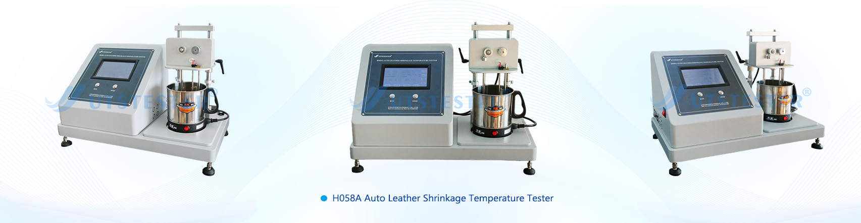
Applicable for testing the shrinkage temperature of leather.
2. Compliance Standards
Complies with ISO 3380, IULTCS/IUP 16, QB/T 2713-2005, and other standards.
3. Technical Parameters
3.1 Temperature Control Range: Ambient to 100°C, with tensile displacement distance 0-110mm;
3.2 Heating Rate: 2±0.2°C/min
3.3 Heating Medium: Distilled water or deionized water
3.4 Test Load: 0-3g
3.5 Instrument Dimensions: 630x330x450mm (L x W x H)
3.6. Instrument Weight: 17kg
3.7. Power Supply: Single-phase 220V, 50Hz
3.8. Control System: PLC
3.9. Operating Interface: 7-inch color touchscreen with Chinese/English language switching
3.10. Touchscreen displays test data curves and real-time temperature readings
4. Composition
The leather shrinkage temperature tester is a device used to measure the temperature at which leather shrinks during heating. This tester typically consists of a heating unit and a measurement system.
During the leather shrinkage temperature test, the sample is usually a small leather patch or fabric. The sample is placed in the heating device and heated to a specific temperature. As the temperature rises, the leather begins to shrink until it reaches the shrinkage temperature. The measuring system records and displays the leather's shrinkage temperature.
5.1 Quality Control: Shrinkage temperature is a key indicator for assessing leather quality. By conducting shrinkage temperature tests, the leather's shrinkage performance can be evaluated to determine compliance with quality standards.
5.2 Material Research and Development: Testing the shrinkage temperatures of different materials helps R&D personnel understand the shrinkage characteristics of various leather types during heating, providing reference for new material development and improvement.
5.3 Production Process Optimization: Testing leather shrinkage temperatures under different heating conditions enables optimization of production processes, enhancing production efficiency and product quality.
5.4 Market Competitive Analysis: Understanding competitors' product shrinkage temperatures aids in formulating competitive strategies and market positioning.
Fabric waterproofness is a special requirement for clothing performance and can be categorized into two main categories: waterproofness and impermeability.
I. Waterproofing
Waterproofing is correctly termed "water repellency." A common method involves adding a hydrophobic compound additive to a liquid tank at the entrance of the finishing machine. The fabric is then fed into the tank, padded, and dried, depositing the hydrophobic compound on the fiber surface. The hydrophobic compound modifies the surface tension of the fibers, limiting their reactivity and reducing the attraction of water molecules to the fibers (fiber surface tension is less than the cohesive force of water molecules). Water forms rolling droplets on the fabric surface (much like a lotus leaf pushing dewdrops). This is also known as "water repellency" or "waterproofing" (abbreviated W/R). See the figure below:
Fabric pores allow air and water vapor to pass through, but if water remains trapped in these pores for extended periods or under pressure, it can still penetrate and even absorb moisture. When wearing waterproof clothing in the rain, water droplets will roll off or shake off, but whether the inner layer of the garment or any undergarments becomes damp depends on the amount of rain and the duration of exposure. The surface water-repellent effect of clothing gradually diminishes with washing and prolonged use, eventually becoming ineffective. Therefore, water repellency essentially reduces the fabric's ability to absorb water; it's not truly waterproof, but simply labeled "waterproof."
II. Waterproofing
Waterproofing is truly waterproof. "Waterproof" means resisting or preventing water penetration, which means it's truly waterproof.
True waterproof fabrics are superior to waterproof fabrics. Their physical and chemical properties are relatively stable and generally withstand washing and long-term use. True waterproofing creates an impermeable barrier on one side of the fabric, requiring a high water pressure rating, such as 3000mm or higher. Waterproofing typically involves applying a rubber-based layer or film to the reverse side of the fabric to prevent water penetration. Common methods include coating and lamination.Coating involves applying a fabric coating adhesive or film to one side of the fabric, creating a waterproof membrane. Common methods include direct coating (dry, wet, or hot melt) and transfer coating. Lamination typically involves pressing a layer of waterproof membrane material (commonly known as a "waterproof membrane") onto the fabric to form a single layer. Regardless of whether the fabric is waterproof or not, the membrane adhered to the fabric always acts as a barrier to water penetration. Another lamination method, hot melt calendering, bonds a polymer waterproof membrane to the fabric, achieving the same barrier effect.True waterproofness (or water penetration) is measured and evaluated by resistance to water pressure, measured in millimeters of water column. Using a fixed surface area of waterproof fabric, water is prevented from penetrating from one contact surface to the other. As water pressure increases, the pressure corresponding to the third drop of water penetrating from the surface is the fabric's resistance to water pressure. Generally speaking, fabrics that withstand a water pressure exceeding 1000 mm are considered to have basic waterproofing.
III. Fabric Waterproofing Test
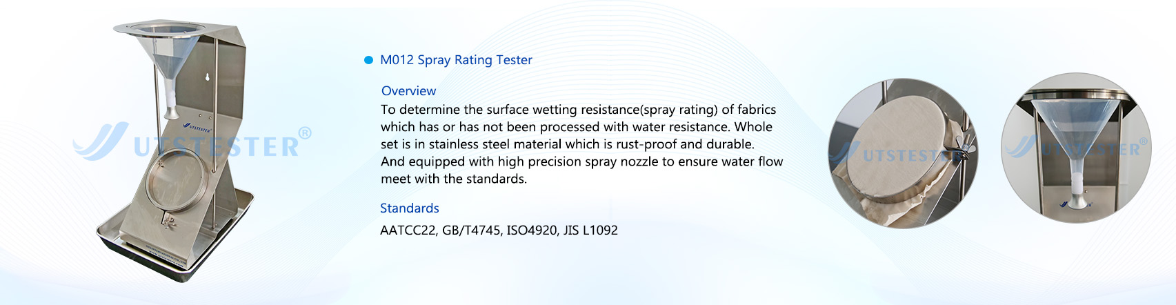
1. Spray Method: AATCC 22-2025 Waterproofness Test
Test Procedure: Under specified conditions and procedures, water is sprayed onto a stretched specimen to form a wet streak on the surface. The size of the wet streak correlates to the fabric's water repellency. The evaluation result is determined by comparing this wet streak with a standard wet streak.
The spray method evaluates the water repellency of fabrics by continuously spraying or dripping water onto the specimen. After a specified period of time, the surface water stain characteristics of the specimen are observed and compared with photographs of specimens at different levels of wetting. The spray method simulates the degree of wetting experienced by clothing in light rain.
This method is applicable to all waterproof and non-waterproof fabrics. The measured waterproof performance results are closely related to the fiber, yarn, fabric treatment and fabric structure. It is usually measured using a spray-type waterproof tester. In the AATCC 22-2005 test method, the test sample is fixed with an iron ring. The sample is kept taut and the surface is flat and wrinkle-free. Distilled water is sprayed from a standard nozzle at a 45-degree angle, aimed at the sample below the nozzle, for 25-30 seconds. The bottom of the iron ring holding the sample is tapped once on a solid object with the test surface facing the solid object. The iron ring is then rotated 180° and tapped again. The sprayed sample surface is then compared with the standard chart and scored to evaluate the waterproof performance of the fabric.
The rating scale is 5, with 5 being the best and 1 being the worst. Level 5: No water droplets on the specimen surface; Level 4: Slightly wet spots on the specimen surface; Level 3: Obvious raindrops on the specimen surface; Level 2: Partially wet specimen surface; Level 1: Completely wet specimen surface.
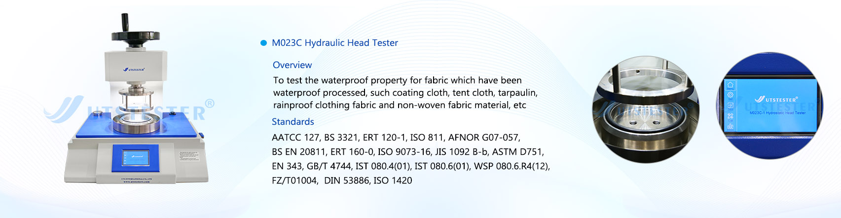
2. Hydrostatic Pressure Test: AATCC 127-2003 Water Resistance: Hydrostatic Pressure Test
Test Procedure: Apply water pressure to one side of the specimen at a steadily increasing rate until three water penetrations are observed on the other side. Water pressure can be applied from the top or bottom of the specimen. Hydrostatic Pressure Tester
Hydrostatic Head Tester
The hydrostatic pressure test measures the water permeability of a fabric under a certain water pressure. This test is suitable for all types of fabrics, including those with water-repellent treatments.
A fabric's water repellency is related to the water resistance of the fibers, yarns, and fabric structure, and differs from the results obtained when water is sprayed or rained on the fabric surface. There are two methods for measuring fabric water repellency: static pressure and dynamic pressure. The static pressure method applies hydrostatic pressure to one side of the fabric and measures the amount of water released under this pressure, the time it takes for the water to drip off, and the hydrostatic pressure at a given water release rate. Hydrostatic pressure can be expressed as the height of a water column or pressure. In actual testing, water permeability per unit area and per unit time (mL/cm²·h) is measured.For waterproof fabrics, the time it takes for a water drop to appear on the other side of the sample is measured, or the number of water drops that appear on the other side after a certain period of time is observed. In the AATCC 127-2003 test method, at least three samples measuring 200 mm x 200 mm are taken diagonally from the sample to be tested. The two sides of the sample are marked with different water resistance levels. The test is conducted using distilled water at (21 ± 2)°C over a test area of 100 cm². The test surface is immersed in water, and the water pressure is increased at a rate of 60 mbar/min (or 10 mm/s).The test is terminated if water droplets appear at three different locations on the sample. However, water droplets appearing within 3 mm of the sample holder are invalid. The test result is the average of three test samples tested under the same conditions. The higher the test value, the greater the pressure required for water to seep out of the sample, indicating better water resistance.
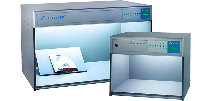
Color matching light boxes, as optoelectronic devices for color inspection, typically incorporate multiple types of standard light sources internally. However, the specific light sources configured vary across different models of color matching light boxes. Below is an introduction to the most commonly used light sources in color matching light boxes.
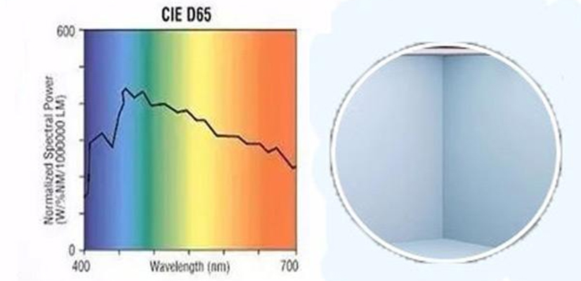
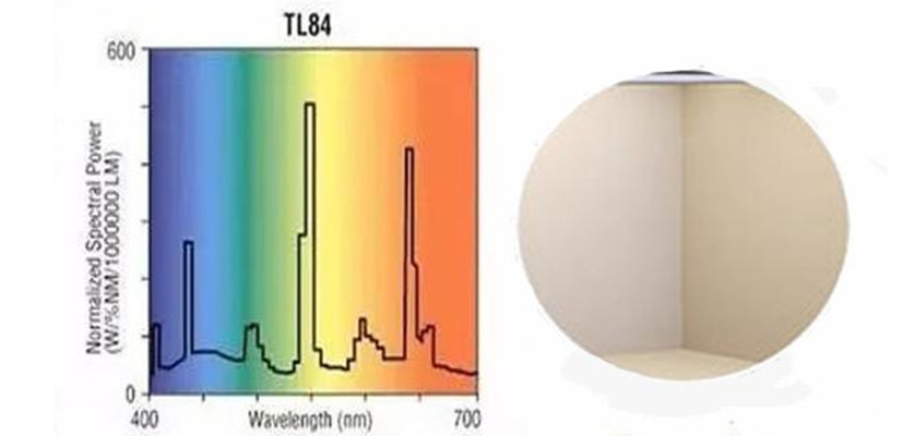
The most commonly used color-matching light sources in standard light boxes include A, D65, TL84, CWF, and U30. These light sources are often combined and arranged by professional manufacturers within a single standard light box for customer use. Different light boxes may have varying configurations to meet the diverse needs of different customers.
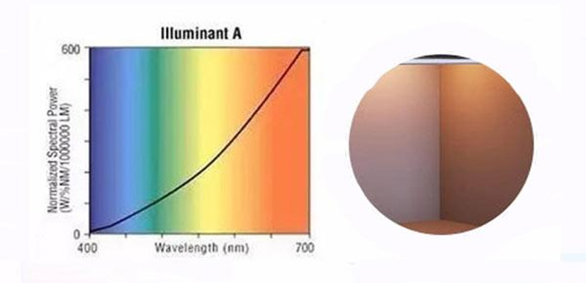
1. A (INCA) Light Source
The A light source is a gas-filled spiral tungsten filament lamp with a color temperature of 2856K. It is a typical incandescent lamp primarily used for accent lighting in residential interiors or retail spaces.
2. D65 Light Source
Among the D-series standard illuminants, CIE recommends D65 as the preferred illuminant. D65 represents average daylight with a correlated color temperature of 6500K, derived from measurements of overcast northern hemisphere daylight at a north-facing window—averaged across all seasons and times of day. D65 is an indispensable standard light source in numerous standards, including ISO 105-A01 “General Rules for Testing the Colour Fastness of Textiles” and ASTM D1729 “Standard Practice for Visual Evaluation of Opaque Materials.” However, due to the unique spectral power distribution of D65, no artificial light source currently exists that can emit light with an identical spectral power distribution to D65; only approximate simulations are possible. In most standard lightboxes, two high-color-rendering fluorescent lamps are used to simulate the D65 light source. In the GretagMacbeth SPLⅢ standard lightbox, however, tungsten-filtered halogen lamps employ tungsten-filtered technology to simulate the D65 light source.
3. Commercial Lighting Sources (F Series)
The TL84 (F) light source belongs to the F series of fluorescent light sources, a proprietary product of Philips. Widely used in Marks & Spencer stores across the UK, it has become a key commercial color-matching light source in the European market. The TL84 light source typically employs Philips' “TLD” (thin-walled) fluorescent tubes coated with rare-earth phosphors. It is a trichromatic fluorescent lamp with a correlated color temperature (CCT) of 4000K. CWF light source (F2) is primarily used in commercial and office settings in the United States, with a correlated color temperature of 4150K. CWF stands for Cool White Fluorescent.
U30/TL83 light source (F12): U30, fully named Ultralume3000, is also a trichromatic fluorescent lamp with a correlated color temperature of 3000K. Sears department stores across the United States utilize U30 tubes manufactured by Westinghouse Electric Corporation. The U30 light source is equivalent to the TL83 light source used in Europe. In the GretagMacbeth Judge II standard lightbox, the Philips TL83 fluorescent lamp is employed to achieve the U30 light source.
4. Other Light Sources
In addition to the above light sources, standard light boxes typically include a UV light source. This ultraviolet lamp is often used alone or in combination with other light sources to inspect fabrics for whitening agents and fluorescent dyes. Additionally, some light boxes feature a HOR (HORIZON) light source. This halogen tungsten lamp simulates daylight during dawn or dusk.
In valve bag production, a tiny hole in the base fabric, a subtle patch offset, or blurred printing can lead to package damage, customer complaints, or even the return of an entire batch. These "insignificant" defects are silently eroding your profits and brand reputation.
Manual inspections are prone to fatigue due to the intense, repetitive work, resulting in a high rate of missed inspections. It's time to say goodbye to this uncontrollable risk. The AI-powered visual inspection system on the FK008 valve bag making machine is your "industrial eye" to address this core pain point.
I. System Analysis: Dual 4K Industrial Cameras Build a Comprehensive Quality Inspection Line
Our vision system is more than just a simple camera; it's an AI brain integrating high-speed cameras, customized lighting, and intelligent algorithms. It's typically deployed at two key workstations:
Base Fabric Inspection Station: Before bag making, the raw web is fully scanned to detect defects such as round threads, holes, heavy threads, splices, and scratches at the source. Finished Product Inspection Station: After bag production, finished bags undergo a final inspection to accurately identify defects such as offset bottom stickers, folded patches, missing corners, missing bottom stickers, uneven overlaps, and smudged or missing prints.
The system compares captured high-definition images against a built-in "perfection standard" in real time. If a defect is detected, an instruction is issued within milliseconds for the automatic rejection device to precisely remove it.
II. Data-Driven: Accuracy and Reliability Beyond the Human Eye
Our performance promises are backed by verifiable data:
Reject rate < 0.05%: This means that for every 10,000 bags produced, fewer than 5 defective items are missed. This figure far exceeds the limits of manual inspection, providing you with a near-absolute quality barrier.
Inspection speeds up to 120ppm: Perfectly matched to the FK008's high-speed production pace, quality inspection no longer becomes a production bottleneck. Saving 2-3 workers per production line: Based on a two-shift system, a single line can directly save up to hundreds of thousands of yuan in labor and management costs annually.
III. Intelligent Cloud Connectivity and User-Friendly Operation
Remote Diagnosis and Data Dashboard: Through cloud control technology, you can view production quality data in real time, and our engineers can also perform remote diagnostics and preventive maintenance.
Operational Requirement and Comprehensive Support: We honestly advise that to maximize system performance, operators must have a college degree or higher in science and engineering to quickly understand the system logic. But rest assured, Gachn Group will provide full support from installation and commissioning to comprehensive operational training, ensuring your team can quickly and independently get up and running.
Summary: More Than Inspection, More Than a Strategic Investment
Equipping the FK008 with an AI visual inspection system is more than just a feature; it's a strategic investment that enhances brand value and reduces overall costs. It elevates your product quality from relying on the experience of experienced technicians to trusting the accuracy and stability of AI, thereby building a solid quality defense against fierce market competition.
Witness the power of technology firsthand
Knowledge gained through books is often shallow. We sincerely invite you to witness for yourself how our AI-powered vision inspection system accurately "hunts" defects on high-speed production lines.
Would you also like to have such an intelligent system to safeguard your production line?
In today’s industries, including home comfort, pharmaceuticals, and food processing, the economic and environmental performance of cooling equipment is critical. Traditional air conditioners and cooling systems have fallen out of favor due to their high energy consumption, expensive maintenance costs, and inability to meet the demands of high-power cooling environments. In contrast, the emerging technology of Variable Frequency Chillers (VFCs) stands out as both reliable and efficient, particularly for high-power cooling scenarios.
1. What is a Variable Frequency Chiller?
A Variable Frequency Chiller is a type of cooling equipment that can automatically adjust its cooling capacity based on real-time demands. This means the system can optimize power consumption without wasting energy when the load is low or causing inefficiency when running at full capacity. It ensures that the cooling output matches the needs of the environment at all times, offering both energy savings and enhanced performance.
2. Advantages of Variable Frequency Chillers
1. High Efficiency:
Variable frequency chillers adjust the cooling power based on real-time compressor performance and environmental temperature, ensuring that cooling is done efficiently and effectively.
2. Quiet Operation:
Compared to traditional chillers, VFCs automatically adjust their power and only engage the compressor when necessary, resulting in lower noise levels during operation.
3. Energy Saving:
Unlike traditional chillers that run at full power upon startup, variable frequency chillers can scale their power usage based on current demand, significantly reducing energy consumption.
4. Reliability:
With more integrated motors, VFCs offer simpler installation and easier maintenance compared to traditional systems. Their advanced design enhances operational reliability.
3. H.Stars Recommended Variable Frequency Chillers
When it comes to selecting the right VFC for large-scale cooling, H.Stars recommends using the "KCP" airflow guidance technology, which dramatically improves cooling performance. The future-proof compressor heads are sourced from top-tier global brands. The selection of the appropriate model should take into account the specific application, investment goals, and cooling efficiency, providing a comprehensive solution for high-power cooling needs.
Conclusion: Why VFCs are the Best Choice for High-Power Cooling
In summary, variable frequency chillers offer high energy efficiency, automatic power adjustment, and quiet operation, making them the ideal choice for environments requiring high cooling capacity. These systems ensure that optimal cooling performance is maintained across various conditions, making them the perfect solution for large-scale or high-power cooling needs.
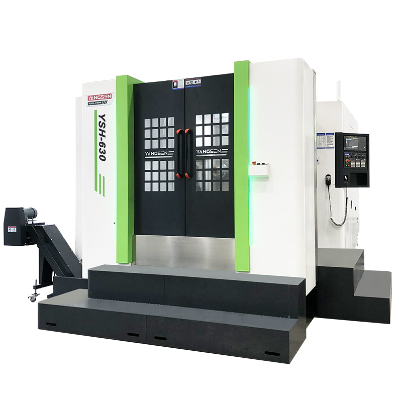
A CNC mill (Computer Numerical Control milling machine) is an advanced machining tool that uses computerized controls to precisely cut and shape materials. Unlike traditional milling, CNC mills follow programmed instructions to produce complex parts with exceptional accuracy and consistency.
This article explains the CNC mill definition and its working principle, outlining how the machine operates, its main components, and common applications in modern manufacturing. Whether you’re a beginner or an industry professional, this guide will help you understand the essentials of CNC milling and its role in precision production.
CNC Mill Definition
A CNC mill, short for Computer Numerical Control milling machine, is a type of machining equipment that removes material from a workpiece with high precision using rotating cutting tools. The “CNC” part means that every movement of the machine—such as spindle rotation, tool change, and table positioning—is controlled by a computer program instead of manual operation.
Unlike traditional milling machines that rely heavily on the operator’s skill, CNC mills follow pre-set digital instructions generated from CAD (Computer-Aided Design) and CAM (Computer-Aided Manufacturing) software. This allows them to produce complex shapes, tight tolerances, and repeatable results consistently.
In modern manufacturing, CNC milling machines are widely used to create parts made from metal, plastic, or composite materials. Their ability to combine accuracy, speed, and automation makes them essential in industries such as aerospace, automotive, medical, and precision engineering.
CNC Mill Working Principle
The working principle of a CNC mill is based on computer-controlled precision. Every machining process begins with a digital design created in CAD software. This design is then converted into a CAM program, which generates a set of G-code instructions—the language that tells the CNC machine exactly how to move, cut, and shape the material.
During operation, the CNC controller reads these codes and directs the machine’s spindle and cutting tools to move along multiple axes (typically X, Y, and Z). The spindle rotates the cutting tool at high speed, while the table or workpiece moves accordingly to remove material layer by layer. This automated coordination allows the mill to achieve extremely accurate cuts and complex geometries that would be difficult or impossible to produce manually.
A typical CNC milling cycle includes several stages:
Design and Programming – Create the part model and generate G-code.
Set up – Mount the workpiece and select the proper cutting tools.
Machining – The CNC system executes programmed movements for material removal.
Inspection – Measure and verify the finished part’s dimensions and surface quality.
This controlled, step-by-step process ensures high precision, repeatability, and efficiency, making CNC milling a core technology in advanced manufacturing and prototyping.
Main Components of a CNC Milling Machine
A CNC milling machine is made up of several key components that work together to ensure precise and stable machining performance. Understanding these parts helps operators and engineers maximize machine efficiency and accuracy.
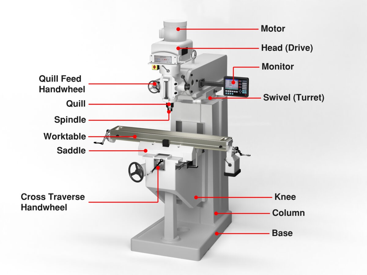
Spindle – The spindle is the heart of the CNC mill. It holds and rotates the cutting tool at high speeds, delivering the power needed for material removal. The spindle’s speed, stability, and precision directly affect machining quality.
Tool Holder and Tool Changer – The tool holder connects the cutting tool to the spindle, while the automatic tool changer allows the machine to switch between tools during operation without manual intervention. This improves production efficiency and flexibility.
Worktable – The table supports and positions the workpiece. It moves along the X and Y axes, allowing precise placement during cutting operations.
Servo Motors and Drive System – These components control the movement of the spindle and table. They ensure smooth, accurate motion along each axis according to the programmed commands.
CNC Controller – Often called the “brain” of the machine, the controller interprets G-code instructions and coordinates all movements of the spindle, axes, and tool changer.
Coolant and Chip Removal System – The coolant maintains a stable temperature in the cutting area, preventing tool wear. At the same time, the chip removal system clears debris to ensure a clean and efficient working environment.
Together, these components enable CNC mills to achieve high-speed, high-precision machining for a wide range of industrial applications.
Types of CNC Milling Machines
CNC milling machines come in several types, each designed for specific applications and levels of precision. Understanding these types helps manufacturers choose the right machine for their production needs.
Vertical CNC Mills
The spindle is oriented vertically, cutting down onto the workpiece.
Ideal for general-purpose machining and small to medium-sized parts.
Commonly used in industries like automotive, electronics, and prototyping.
Horizontal CNC Mills
The spindle is horizontal, allowing cutting on multiple sides of a workpiece.
Suitable for heavy-duty machining and high-volume production.
Provides better chip removal and stability for larger workpieces.
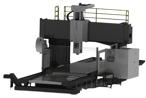
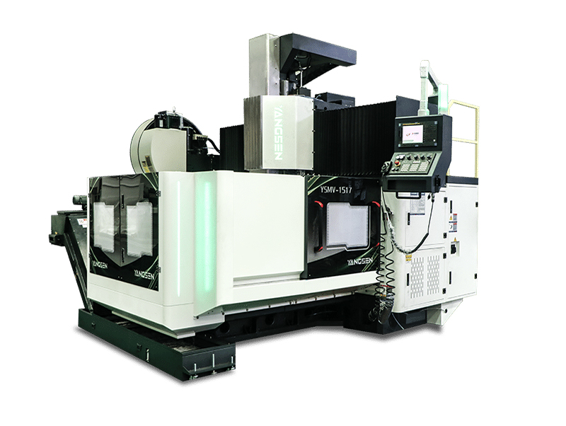
Large machines with a bridge-like structure, suitable for very large workpieces.
Used in industries like shipbuilding, aerospace, and heavy machinery.
Compact and Mini CNC Mills
Smaller footprint machines for light-duty and precision work.
Common in educational settings, small workshops, and prototyping labs.
Applications of CNC Milling Machines
CNC milling machines are widely used across multiple industries due to their precision, efficiency, and flexibility. Key applications include:
Aerospace Industry
Manufacturing turbine blades, engine housings, and structural components.
High precision and tight tolerances are critical for safety and performance.
Automotive Industry
Producing molds, gearboxes, engine parts, and custom components.
CNC mills improve efficiency and ensure consistent quality for high-volume production.
Medical Industry
Fabricating implants, surgical instruments, and prosthetics.
Allows complex geometries and precise dimensions essential for patient safety.
Electronics Industry
Producing enclosures, heat sinks, connectors, and circuit boards.
Small, detailed parts require the accuracy CNC milling provides.
Tooling and Die Making
Creating precision molds, dies, and fixtures for manufacturing.
CNC milling enables faster production cycles with minimal manual adjustment.
Prototype and Product Development
Rapidly producing prototypes for testing and design validation.
Allows quick iteration and modification before mass production.
By leveraging CNC milling, companies across these industries achieve higher accuracy, reduced errors, and increased productivity, making it an essential technology in modern manufacturing.
Advantages of CNC Milling
CNC milling machines offer high precision and repeatability, allowing manufacturers to produce parts with consistent quality. This level of accuracy is essential for industries like aerospace, automotive, and medical devices, where even minor deviations can cause major issues.
Automation in CNC milling significantly improves efficiency and reduces human error. Multi-axis milling enables the creation of complex geometries in fewer setups, saving time and labor costs while maintaining consistent results across production runs.
In addition, CNC mills are highly versatile, capable of working with a wide range of materials ,including metals, plastics, and composites. They are suitable for both prototype production and large-scale manufacturing, combining speed, flexibility, and reliability to enhance overall productivity.
CNC Milling vs CNC Turning
Feature
CNC Milling
CNC Turning
Motion
The tool rotates; the workpiece moves
Workpiece rotates; tool is stationary
Typical Parts
Complex shapes, flat surfaces
Cylindrical or symmetrical parts
Axes
Usually 3–5 axes
Typically 2–3 axes
Setup Complexity
Medium to high
Medium
Best Use Case
Multi-sided and detailed parts
Round components, high-volume production
How to Choose the Right CNC Milling Machine
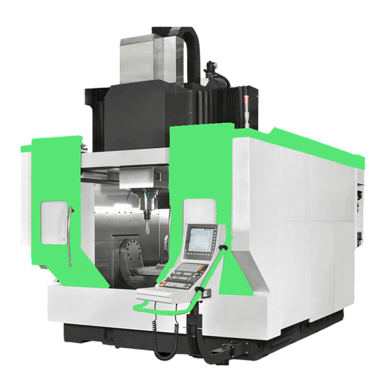
Selecting the right CNC milling machine depends on several key factors, including your production needs, budget, and the materials you work with. First, consider the type of milling machine—vertical, horizontal, or 5-axis—based on the complexity of the parts and the required precision. Vertical mills are versatile and suitable for general-purpose machining, while horizontal and 5-axis machines are better suited for handling larger or more intricate components.
Next, evaluate the machine’s specifications, such as spindle speed, axis travel, table size, and load capacity. These factors determine the size of workpieces you can handle, the materials you can mill, and the overall production efficiency. For high-volume or precision-critical parts, investing in a machine with multiple axes and higher rigidity will ensure better performance and repeatability.
Finally, consider software compatibility, support, and maintenance. Ensure the CNC controller is compatible with your CAD/CAM software, and that the manufacturer provides reliable technical support and spare parts. A well-supported machine reduces downtime and long-term costs. By carefully assessing these factors, you can select a CNC milling machine that maximizes productivity, quality, and return on investment.
CNC Milling Machine Maintenance and Safety Tips
Proper maintenance and safe operation are essential to ensure the longevity and performance of CNC milling machines. Regular cleaning and lubrication of moving parts prevent wear and maintain accuracy, while checking tool holders, spindles, and worktables ensures stable and precise machining.
Operators should monitor tool wear and machine calibration to avoid defects and maintain consistent quality. Using the correct cutting tools and replacing worn components in time helps prevent damage to both the machine and the workpiece.
Safety is equally important. Always follow standard operating procedures, wear appropriate personal protective equipment, and ensure the machine’s emergency stops and guards are functional. Adhering to maintenance schedules and safety guidelines not only extends the machine’s lifespan but also ensures efficient, reliable, and safe production.
Conclusion
Understanding the CNC mill definition and working principle is essential for anyone involved in modern manufacturing. CNC milling machines combine precision, automation, and versatility to produce high-quality parts efficiently, making them indispensable across industries such as aerospace, automotive, medical, and electronics.
Choosing the right machine, maintaining it properly, and following safe operating practices ensure consistent performance and long-term reliability. For businesses looking to improve productivity and reduce production errors, investing in a high-quality CNC milling solution is a strategic decision.
Medical Device CNC Machining is the process of shaping medical components using computer numerical control, or CNC for short. The machine uses programmed commands to move cutting tools exactly where they need to go. This process removes material layer by layer until the desired shape appears. For example, when creating a titanium hip implant, a CNC machine can mill it with such precision that it fits the patient’s bone structure almost perfectly.
The primary difference between medical CNC machining and standard CNC machining lies in the level of precision and cleanliness. A typical part for an automotive engine might tolerate small imperfections, but a surgical screw cannot. In medical production, the parts must be sterile, burr-free, and often smaller than a grain of rice. This is where specialized techniques like micro-milling and Swiss-type turning come into play. These methods help make tiny and complex components without compromising accuracy.
Importance of CNC Machining in the Medical Industry
The medical industry depends on precision, and CNC machining provides exactly that. Every time a surgeon picks up an instrument or a patient receives an implant, CNC technology has played its part. Without it, producing consistent, safe, and accurate tools would be nearly impossible.
CNC machining is the backbone of medical device manufacturing because it meets the strict requirements of healthcare. Think about devices such as orthopedic implants, dental fixtures, and cardiovascular tools. Each one must match not just medical standards but also the patient’s unique anatomy. CNC machines make that possible through computer-guided control and repeatable accuracy. This process reduces human error and increases patient safety.
I’ve noticed that hospitals and device manufacturers rely heavily on biocompatibility and quality assurance. Standards like ISO 13485 and FDA 21 CFR Part 820 regulate how medical parts are made and tested. CNC machining helps companies meet those standards by allowing them to record, trace, and reproduce every step. If a defect occurs, engineers can trace it back to the exact tool path or batch number.
Types of CNC Machines Used in Medical Device Manufacturing
CNC Milling Machines
CNC milling machines are the workhorses of medical manufacturing. They cut and shape solid blocks of metal or plastic into complex geometries. When producing things like hip joints, knee implants, and surgical tools, the machine’s 5-axis movement allows it to reach all sides without repositioning the part. I once watched a 5-axis mill carve out a hip implant from titanium—it looked like magic in motion.
These machines are known for their ability to handle contours and curved shapes. That’s especially useful for implants that need to fit perfectly inside the human body. Each pass of the cutting tool removes microns of material until the final surface is smooth and precise. The result is a piece that’s ready for polishing or coating without heavy manual work.
CNC Turning and Swiss-Type Lathes
Turning machines, especially Swiss-type lathes, handle long and thin components like bone screws, rods, and catheters. The name “Swiss” comes from the Swiss watch industry, where precision is everything. In medical production, the same level of accuracy is used to create devices that can safely stay inside the body for years.
These machines can handle very small diameters—sometimes under one millimeter—and maintain perfect concentricity. That means each screw thread or pin sits exactly where it should. It’s fascinating how these machines work: the material moves instead of the cutting tool, reducing vibration and allowing extreme precision. It’s like watching a ballet, but with steel.
CNC Grinding and Polishing Machines
Grinding and polishing machines finish what others start. After milling or turning, many medical parts require mirror-like surfaces to avoid tissue irritation. Grinding removes microscopic imperfections, and polishing adds a fine, reflective sheen. For surgical blades or implants, that final polish means smoother contact and less friction during use.
In cleanrooms, these finishing machines run quietly and carefully. I’ve seen technicians measure the final surface using light reflection tools to ensure no scratches remain. That level of perfection isn’t just for looks—it’s for safety.
CNC EDM (Electrical Discharge Machining)
EDM uses electrical sparks to shape materials that are too hard for normal cutting tools, like titanium or stainless steel. It’s perfect for creating small holes, cavities, and intricate features on surgical instruments. Because there’s no physical contact between tool and material, EDM can achieve shapes that standard tools can’t reach.
This process is especially common for tools like laparoscopic tips, orthopedic screws, and micro-instruments. Watching an EDM machine work is oddly calming—it makes thousands of tiny sparks, each removing a speck of metal. Slowly, the final part emerges, precise down to fractions of a micron.
Multi-Axis Machining Centers
Multi-axis centers combine milling, turning, and drilling into one machine. This setup saves time by eliminating multiple setups. It’s perfect for orthopedic implants, dental abutments, and custom surgical jigs. When I visited a facility that made spine implants, I noticed how one multi-axis machine could produce a full set of parts in a single run.
The main advantage of multi-axis machining is accuracy with efficiency. By machining a part from all angles without stopping, it minimizes misalignment. That means the final component needs little or no adjustment before inspection.
Common Medical Devices and Components Made with CNC Machining
When I first stepped into a medical machining workshop, I was surprised by how many different medical parts come from CNC machines. Almost every metal or plastic component used in hospitals or surgeries has likely passed through one of these precision systems. Here’s how CNC machining supports various medical fields:
Orthopedic Implants
CNC machining is used to make hip joints, spinal cages, bone screws, and knee implants.
• These parts must fit the patient’s bone structure with extreme accuracy.
• Titanium and cobalt-chrome alloys are the most common materials for strength and biocompatibility.
• The smooth finish reduces friction and prevents tissue irritation.
• I once held a finished hip cup—it was so polished it reflected light like a mirror. That surface wasn’t just for looks; it helps the implant move smoothly within the body.
Surgical Instruments
• Instruments like forceps, scalpels, clamps, and drill guides rely on CNC precision for consistent sharpness and shape.
• CNC machining ensures every piece is balanced and performs reliably during surgery.
• Stainless steel and titanium are often used because they handle repeated sterilization without damage.
• Laser inspections confirm every edge is sharp and smooth.
• Watching these parts get checked under magnifiers made me realize—surgeons rely on perfection every single time.
Dental and Maxillofacial Components
• CNC machines create crowns, abutments, and dental implants that match a patient’s mouth perfectly.
• Dentists can send 3D scans directly to the manufacturer for same-day milling.
• Materials include ceramics, stainless steel, and titanium.
• These machines cut with such precision that dental parts often need only a light polish before use.
• I once saw a machine mill a crown from a ceramic block—it took less than ten minutes and fit flawlessly.
• These parts are often smaller than a fingernail but must perform reliably for years inside the human body.
• Materials like titanium and stainless steel resist corrosion and maintain stability in body fluids.
• Engineers often say, “If you can see the flaw, it’s already too big.” That sums up the precision needed here.
• Every spark, cut, or polish is controlled with micrometer accuracy to avoid any error.
Diagnostic and Laboratory Equipment
• CNC machining also supports MRI machines, CT scanners, and robotic surgery systems.
• Components include brackets, frames, instrument arms, and sensor housings.
• These parts need to stay stable and vibration-free for accurate test results.
• Aluminum and high-performance plastics are preferred for lightweight strength.
• I noticed that even the smallest mount or bracket inside a scanner must meet exact size standards—it’s how machines keep producing reliable readings for years.
Prosthetics and Assistive Devices
• CNC machines create custom prosthetic joints, sockets, and connectors that improve patient mobility.
• Personalized designs allow a better fit and comfort for daily wear.
• Advanced 5-axis milling enables natural, curved surfaces that align perfectly with body contours.
• Combining metal and polymer machining provides strength without adding weight.
• It’s heartwarming to see how technology turns raw materials into life-changing support devices.
Robotic Surgical Components
• CNC machining produces arms, joints, and end-effectors for robotic-assisted surgeries.
• These parts must move precisely and smoothly without any mechanical play.
• Stainless steel and lightweight aluminum are used for stability and responsiveness.
• Each joint undergoes multiple tolerance tests before final assembly.
• I once saw a robot arm component fail inspection for being off by 0.0005 mm — the engineer just smiled and said, “That’s why we check.”
Materials Used in Medical Device CNC Machining
Titanium and Titanium Alloys
Titanium is the superstar of medical materials. It’s strong, light, and doesn’t rust or cause allergic reactions. You’ll find it in implants, bone screws, and even artificial joints. The downside? It’s tough to cut. Machining titanium requires sharp tools and slower speeds to avoid overheating. But when done right, the result is a component that lasts for decades inside the body.
Stainless Steel (316L, 17-4PH)
Stainless steel remains a popular choice for reusable surgical instruments because it’s durable, affordable, and easy to sterilize. Grades like 316L and 17-4PH resist corrosion and can handle repeated exposure to heat and cleaning chemicals. CNC machines shape them into blades, clamps, and other durable components.
Aluminum Alloys
Aluminum alloys are used mainly in non-implantable components such as diagnostic equipment or housings for devices. They’re lightweight and conduct heat well, making them ideal for machines that need to stay cool. They’re also easy to machine, which keeps costs down.
Plastics and Polymers (PEEK, PTFE, Ultem, Delrin)
Plastics like PEEK, PTFE, Ultem, and Delrin are widely used for non-implantable components such as surgical trays, fixtures, and instrument handles. PEEK, in particular, is a favorite for temporary implants because it’s strong and resists chemicals.
Specialty Alloys and Ceramics
Some parts need special materials like Nitinol, a shape-memory alloy that can return to its original form after bending, or medical-grade ceramics, which resist wear and heat. These materials are often used in dental and orthopedic applications.
CNC Machining Processes for Medical Devices
Prototyping and Low-Volume Production
When developing new medical devices, designers need prototypes fast. CNC machining can create a test-ready prototype in just a few hours. This allows teams to check function, fit, and design before moving into full production.
Full-Scale Production
Once a prototype passes all tests, full-scale production begins. High-speed CNC machines run multiple parts at once, maintaining the same precision across thousands of units. Automation ensures consistency while reducing manual handling.
Post-Processing Techniques
After machining, medical parts go through finishing steps like deburring, polishing, electropolishing, passivation, or anodizing. These processes remove sharp edges, smooth surfaces, and prepare the part for sterilization. For implants, surface finishing can even improve how tissue bonds with the material.
Precision and Quality Control in Medical CNC Machining
If there’s one thing I’ve learned from spending time around medical machinists, it’s that “close enough” doesn’t exist in their vocabulary. Precision isn’t just expected — it’s demanded. In the medical field, a tiny error can cause a major problem, so quality control is almost a sacred process.
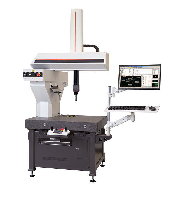
CNC machining for medical devices focuses on tolerances as tight as ±0.001 mm. To put that into perspective, that’s smaller than a grain of dust. Every part goes through detailed measurement using tools like coordinate measuring machines (CMMs), optical scanners, and laser micrometers. These instruments check every curve, edge, and angle to confirm that each component meets design specifications.
Advantages of CNC Machining for Medical Devices
• Extreme precision and repeatability
• Compatibility with biocompatible materials
• Flexibility for custom, patient-specific designs
• Rapid prototyping and faster time-to-market
• Clean and safe manufacturing environment
• Reduced human error and waste
• Scalability from prototype to production
Choosing the Right CNC Machining Partner for Medical Devices
Verified Certifications
• Choose a company with ISO 13485 certification for medical manufacturing.
• Ensure they follow FDA 21 CFR Part 820 for quality and documentation.
• Ask for proof of regular audits and inspection records.
Experience with Biocompatible Materials
• Verify that they can handle titanium, stainless steel, and medical-grade polymers.
• Look for shops that use dedicated tools and coolants to avoid contamination.
• Ask about past projects involving implants or surgical parts.
Advanced Equipment and Technology
• The partner should have multi-axis machines, Swiss lathes, and micro-machining setups.
• Cleanroom machining facilities are a strong sign of professionalism.
• Automated inspection and measurement tools add another layer of reliability.
Proven Quality Assurance System
• Every component should be traceable from start to finish.
• Internal audits and inspection logs ensure ongoing consistency.
• Ask if they use CMM or laser scanning for part verification.
Real Industry References
• Check case studies or client testimonials from hospitals and medical suppliers.
• Visit their facility if possible—cleanliness and organization say a lot.
• Genuine experience in medical-grade machining should be visible in their past work.
Final Thoughts
After seeing how much care and detail go into every stage of medical device CNC machining, I’ve come to respect it as both an art and a science. These machines might look like ordinary equipment, but they carry the responsibility of human lives. The precision isn’t just about numbers—it’s about trust.
So, the next time you walk into a hospital and see a metal implant or a shiny surgical tool, remember that it didn’t just appear—it was carefully crafted, checked, and perfected through CNC machining.