What is the difference between self-priming pump and non-clog submerged sewage pump?
non-clog submerged sewage pump are engineered to operate below the liquid medium, enabling low-level transportation. Their structural design features a long-shaft cantilever configuration. The submersion depth must be strictly limited to 2 meters, as exceeding this threshold causes a significant drop in efficiency. However, the primary challenge lies in the flexible shaft's design. During operation, the bearings endure continuous one-sided wear, which leads to bearing vibration and further exacerbates the wear cycle, resulting in persistently high failure rates. Moreover, the wear-prone components are predominantly located below the liquid medium, making disassembly and maintenance extremely difficult.
The development of self-priming pumps represents a revolutionary advancement over traditional pumping systems. Firstly, these pumps eliminate the long shafts and troublesome bearings found in non-clog submerged sewage pump. Secondly, their key components remain above ground level, with no mechanical parts submerged in the medium being transported. This design enables faster and easier maintenance and repairs. Furthermore, they achieve a significant lift height improvement, with maximum suction reaching approximately 7 meters (higher in specialized configurations), marking a qualitative leap compared to non-clog submerged sewage pump.
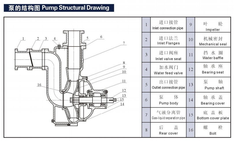
The self-priming pump operates on a unique principle utilizing patented impellers and separation discs to achieve forced gas-liquid separation during suction. Its design, size, weight, and efficiency closely resemble those of pipeline pumps. This pump requires no auxiliary equipment such as foot valves, vacuum valves, or gas separators. During normal operation, it eliminates the need for liquid priming, boasting exceptional self-priming capability that effectively replaces widely-used non-clog submerged sewage pump (low-level liquid transfer pumps). It can also serve as auxiliary equipment for separators, tanker transfer pumps, self-priming pipeline pumps, and motorized pumps.
Another advantage of the self-priming pump, or its key feature, is that after the pump chamber is initially filled with the liquid, it can directly run dry to draw the medium into the pump (with a dry running time not exceeding 7 minutes). This prevents accidents caused by accidental operation that might burn out the motor during dry running, significantly reducing operational risks while enhancing the pump's efficiency.
Advantages and disadvantages of non-clog submerged sewage pump
Advantages
1. The non-clog submerged sewage pump is directly installed on the storage of the medium to be transported, without extra floor space.
2. The traditional non-clog submerged sewage pump features a unique centrifugal double-balanced impeller, delivering clean media containing solid particles with exceptionally low vibration and noise while maintaining high efficiency. When using the open-type double-balanced impeller, it effectively transports contaminated liquids containing solid particles and short fibers, ensuring smooth operation without clogging.
Disadvantages
1. It is necessary to increase the intermediate tank, and the liquid level of the intermediate tank should be controlled during operation;
2. The maintenance is complex and requires regular replacement of seals.
3. High maintenance rate and high cost;
4. Need sealed air;
5. The traditional non-clog submerged sewage pump is not suitable for the transportation of flammable and explosive materials.
6. The new type of non-clog submerged sewage pump is not suitable for conveying highly corrosive materials with particles.
non-clog submerged sewage pump have distinct advantages and disadvantages, and even more disadvantages than advantages. At the same time, many industries now prohibit the use of non-clog submerged sewage pump and replace them with self-suction pumps, which may not be entirely due to the difficulty of maintenance caused by their own structure.
The reason of the high noise of non-clog submerged sewage pump
1. Mechanical aspects
The unbalanced mass of rotating parts of FRP non-clog submerged sewage pump, poor quality of crude production, poor installation quality, asymmetrical shaft of unit, swing exceeding allowable value, poor mechanical strength and stiffness of parts, bearing and sealing parts wear and damage, etc., will produce strong vibration.
2. The quality of the water pump and other aspects
The unreasonable design of the inlet channel makes the deterioration of the inlet conditions and the generation of vortex. It will lead to the vibration of the long shaft non-clog submerged sewage pump. The uneven settlement of the foundation supporting the non-clog submerged sewage pump and motor will also lead to the vibration.
3. Causes of bearing damage of non-clog submerged sewage pump
The bearing was damaged due to prolonged operation of the non-clog submerged sewage pump, which caused the lubricating oil to dry out. Carefully identify the source of the noise and replace the bearing.
4. Caused by hydraulic factors
The most common causes of vibration of non-clog submerged sewage pump unit are cavitation and pressure fluctuation in the pipeline.
5. Electrical aspects
The motor is the main equipment of the unit. The magnetic imbalance inside the motor and the imbalance of other electrical systems often cause vibration and noise.
6. Causes of impeller shaking of non-clog submerged sewage pump
The corrosion-resistant non-clog submerged sewage pump impeller nut shakes due to corrosion or overturning, causing significant impeller movement, which results in excessive vibration and noise.
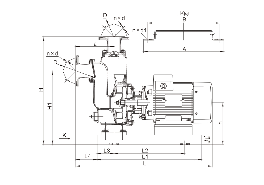
Precautions and installation diagram for self-suction pump
Installation notes for self-priming pumps
1. Before installing a self-priming pump, construct a concrete foundation matching its base dimensions, with anchor bolts pre-installed during the process. This foundation is specifically designed for large self-priming pumps, as smaller models do not require such a foundation.
2. Before installing the self-priming pump, carefully inspect all bolts for looseness and check the pump body for foreign objects to prevent impeller damage during operation.
3. Position the self-priming pump on the concrete foundation, place an isolation pad between the base plate and the foundation, and adjust the pad's height to align the pump horizontally. After adjustment, tighten the bolts.
4. The suction and discharge pipes of a self-priming pump must not be propped up by the pump itself. Instead, they require separate supports to ensure proper alignment. The diameter of both inlet and outlet pipes must match the pump's specifications, with particular attention to the inlet pipe. Any reduction in diameter during installation will compromise the pump's self-priming height. If the inlet pipe is installed with a smaller diameter, the outlet pipe must also be proportionally reduced. We recommend using pipes with diameters that match the manufacturer's standard specifications for optimal performance.
5. When encountering a self-priming pump with a dust cover at the inlet/outlet, remove the cover and connect it to the pipeline. Note that if using a self-priming pump with rapid water suction, the outlet pipe must extend vertically upward for at least 1 meter before bending. Otherwise, the water in the pump body may be completely drained during the priming process.
6. For maintenance convenience and operational safety, a regulating valve should be installed at both the inlet and outlet of the self-priming pump. Additionally, a pressure gauge must be placed between the outlet valve and the pump to ensure it operates within its rated flow and head range, thereby guaranteeing normal operation and extending the pump's service life.
7. Before starting the self-priming pump after installation, rotate the pump shaft and fill the pump chamber with liquid to ensure complete drainage. Inspect for leaks and verify the impeller has no friction or jamming. If any issues are detected, disassemble the pump to diagnose and resolve the problem.
Precautions for self-suction pump
1. Before using a self-priming pump, ensure the pump chamber is completely filled with liquid. Never run the pump dry. However, if the pump is designed for dry operation, it may be used without liquid.
2. Before using a self-priming pump, open both inlet and outlet valves. After connecting the power supply, press the start button to check if the motor rotates in the correct direction as indicated.
3. The outlet valve of the self-suction pump must not be completely closed when in use. If the liquid delivery must be stopped, the inlet valve should be closed, but the duration should not exceed 2 minutes. If it exceeds, the machine should be stopped to avoid damage to the self-suction pump.
4. After stopping the self-priming pump, fully close both inlet and outlet valves. For media prone to solidification, first close the inlet valve and let the pump run for 1-2 minutes to drain the liquid from the pump chamber.
Reasons and solutions for the failure of self-suction pump
1. The self-priming pump fails to draw water because its suction pipe is not properly sealed, causing the pump to remain in a continuous air-suction state.
Solution: Check the inlet pipe of the self-suction pump and repair the leakage point of the sealing, such as the welding place, pipe joint and other suspected leakage places. Carefully check, for example, you can run for about 5 minutes and then stop the machine. Listen to the suction sound close to the pipe.
2. After a period of use, the self-suction pump will suffer from corrosion or wear, and the mechanical seal will leak water, which will be the reason why the self-suction pump can not suck water.
Solution: Replace the damaged part with a new one.
3. The reason why the self-suction pump cannot suck water is that the pipeline or the bottom valve or even the pump body is blocked due to the large amount of impurities in the liquid conveyed.
Solution: Find the specific blockage point and clean out the debris to solve the problem.
4. Improper installation of imported pipelines, such as excessive elbows (number should be controlled to 1-2), or using 45-degree elbows when there are two elbows, may cause the self-priming pump to fail to draw water. Additionally, arbitrarily enlarging the pipeline diameter without matching the pump's specifications can also lead to this issue.
5. If the self-priming pump fails to draw water during its second operation after initial suction, it indicates air has entered the pump body. This typically occurs when the outlet pipe lacks a check valve, allowing air to enter through the atmospheric connection. After shutdown, water may backflow and air could be trapped inside. To resolve this, the pump must be primed with water before restarting to purge the trapped air and ensure proper water intake.
The solution of this kind of self-priming pump is to install a globe valve at the outlet and close the outlet valve before stopping the pump.
6. When the self-priming pump is installed and used, the water suction height exceeds the allowable suction height of the pump.
It is recommended to replace the self-priming pump with a higher self-priming height or to use a non-clog submerged sewage pump instead.

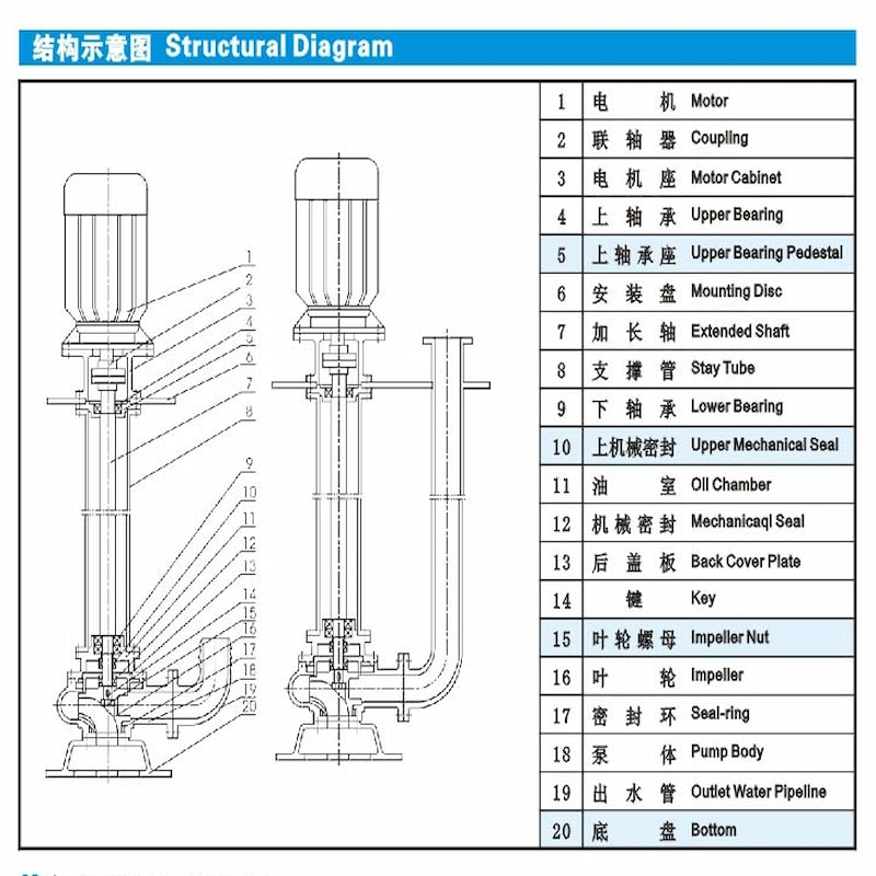
NON-CLOG SUBMERGED SEWAGE PUMP Operating Instructions and Maintenance
Operating Instructions and Attention Remarks
1. Before operation, check carefully whether there are any damages to pump and motor, and the conditions of fastening pieces.
2. Turn the pump to check whether there is any sound of abrasion, and also the concentricity of pump shaft and motor shaft. The cylindrical deviation of the two couplings should not exceed 0.5mm.
3. The pipeline connected to the liquid outlet shall be supported separately, its weight is not allowed to be placed upon the pump body.
4. Except for special conditions, pump shall be fitted with a full automatic pump control cabinet. Never connect it directly to power grid or by use of knife switch to ensure normal operation.
5. Don’t let the pump always running at low head. Normally, the service head should not be lower than the 60% of the rated head, and should better be controlled within the range of the suggested service head, so that motor would not be burnt out due to the overload of pump.
Maintenance
1. Pump should be managed and operated by a special person, who shall check regularly the circuit and working conditions of the pump.
2. Every time after use, especially after being used to handle viscous serosity, let the pump running for several minutes in clean water to avoid anything deposited inside the pump and to keep the pump clean.
3. Normally, after 300-500 work hours, fill or replace the oil in the chamber with 10-30# oil, thus to maintain good lubrication at mechanical seal and to improve the service life of mechanical seal.
4. The sealing ring between impeller and pump body is performed to seal, which can directly affect the performance of pump if it is damaged, and shall be replaced if necessary.