Regarding some questions about screw pumps, Anhui Shengshi Datang would like to share some insights with everyone.
Causes and Hazards Analysis of Rod String Reverse Rotation in Screw Pump Wells
1. Analysis of Causes for Rod String Reverse Rotation in Screw Pump Wells
During oilfield extraction using Screw Pumps, reverse rotation of the rod string is a relatively common failure. The causes of this reverse rotation are complex, but the primary reason is the sudden shutdown or sticking of the pump during operation, which causes deformation and torsion of the rod string. The rapid release of this deformation and torsion then leads to reverse rotation. Specifically, if the Screw Pump suddenly stops or sticks during operation, a pressure difference arises between the high-pressure liquid retained in the production tubing and the wellbore hydrostatic pressure in the casing annulus. Driven by this pressure difference, the Screw Pump acts as a hydraulic motor, driving the rotor and the connected rod string to rotate rapidly in reverse.
The reverse rotation of the Screw Pump rod string is influenced by the tubing-casing pressure difference, exhibiting variations in reverse rotation duration and speed. Generally, a larger tubing-casing pressure difference results in faster reverse rotation speed and longer duration for the rod string. As the pressure difference gradually decreases, the reverse rotation speed and duration correspondingly decrease until the pressure difference balances, at which point the reverse rotation gradually ceases. When reverse rotation occurs, the rod string vibrates intensely. If resonance occurs during this vibration—meaning the vibration frequency of the reversing rod string synchronizes with the natural frequency of the wellhead—the rotation speed can instantly surge to its maximum. This situation can trigger serious safety accidents, cause significant harm to the worksite, and even result in casualties.
2. Hazards of Rod String Reverse Rotation in Screw Pump Wells
The hazards caused by rod string reverse rotation vary in degree depending on the speed and duration of the reversal. Severe cases can lead to onsite safety incidents with serious consequences. Specifically, the hazards mainly manifest in the following three aspects:
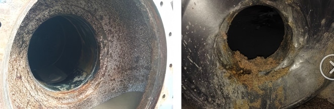
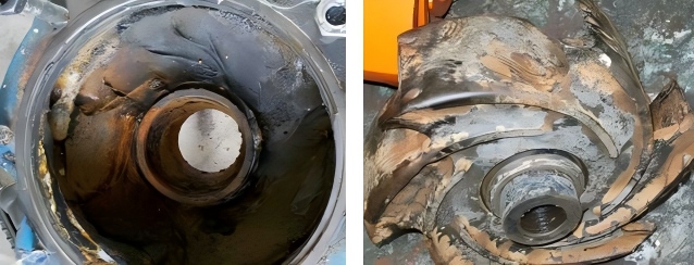
(1) Reverse rotation can cause the rod string to become displaced from its original position, leading to the swinging of the Screw Pump polish rod. This can cause significant wear and tear on the Screw Pump equipment, damaging various components and parts.
(2) During reverse rotation, if the speed is too high or the duration too long, the temperature of the reversing components can continuously rise, potentially igniting flammable gases at the wellhead. This could trigger an explosion at the worksite, leading to unforeseeable serious consequences.
(3) If reverse rotation is not effectively controlled, it can cause the drive pulley to shatter. Fragments of the pulley flying around the worksite pose a risk of injury to personnel, damage the oilfield production site, reduce extraction efficiency, and increase the probability of various safety incidents.
Commonly Used Anti-Reverse Rotation Devices for Screw Pump Well Rod Strings
1. Ratchet and Pawl Type Anti-Reverse Device
This type of device prevents reverse rotation by utilizing the one-way engagement of a ratchet and pawl. Specifically, the ratchet and pawl engage via an external meshing configuration. When the Screw Pump drive operates normally, centrifugal force causes the pawl to disengage from the ratchet brake band, so the anti-reverse device remains inactive. However, when the Screw Pump suddenly stops during operation, the rod string begins to reverse due to inertia. During this reverse rotation, gravity and spring force cause the pawl to engage with the ratchet brake band, activating the anti-reverse device. The device then dissipates the torque generated by the high-speed reverse rotation through frictional force.
The ratchet and pawl device has a simple structure, is easy to install, has a low overall cost, and offers good flexibility and controllability. However, it typically requires manual intervention at close range for activation/operation. Improper operation can cause the friction surfaces to slip, presenting a safety risk. Additionally, this type of device can generate significant noise during operation and subjects the components to considerable impact and wear, necessitating frequent part replacements.
2. Friction Type Anti-Reverse Device
The friction type anti-reverse device consists of two main parts: an overrunning clutch that identifies rotation direction and a brake shoe assembly. In this device, the brake shoes are connected to the brake bodies via riveting, and the two brake bodies grip the outer ring. During normal Screw Pump operation (clockwise rotation), the device remains inactive. When a sudden shutdown causes reverse rotation, the drive mechanism reverses. In this state, rollers move between the star wheel and the outer ring, activating the device. The resulting damping effect restricts the rotation of the star wheel, thereby achieving the anti-reverse function. However, since the operation of this device often requires manual control, improper handling can lead to failure. Furthermore, replacing this device involves significant safety risks. Consequently, its application in Screw Pump wells is currently relatively limited.
3. Sprag Type Anti-Reverse Device
The sprag type anti-reverse device operates based on the principle of an overrunning clutch. Specifically, during normal Screw Pump operation (forward rod string rotation), the sprags inside the device align normally and remain disengaged from the outer ring, keeping the device inactive. When the pump suddenly stops and the rod string starts to reverse rotate, the resulting reverse torque causes the device to rotate in the opposite direction. This makes the sprags align in the reverse direction, locking them against the outer ring and preventing reverse rotation of the rod string.
The sprag type device has a simple construction, is easy to install, offers good controllability, and operates with high safety, minimizing the risk of accidents. It also has a long service life and does not require frequent part replacements. The drawback is that it cannot fundamentally solve the reverse rotation problem. If the reverse torque exceeds the capacity the sprags can withstand, it can cause sprag failure and device malfunction. Additionally, daily maintenance of this device can be inconvenient.
4. Hydraulic Type Anti-Reverse Device
The working principle of the hydraulic anti-reverse device is somewhat similar to a car's braking system. When the Screw Pump suddenly stops and the rod string is about to reverse rotate, the hydraulic motor within the device activates. Hydraulic fluid pressure drives friction pads against a brake disc, releasing a large amount of the reverse rotation potential energy, thereby dissipating the reverse rotation of the rod string.
The advantages of the hydraulic type device include stable and reliable operation, high safety, no noise generation, and no hazard to onsite personnel. Maintenance, replacement, and daily upkeep are relatively convenient and safe. This type of device can more thoroughly address the reverse rotation problem, enhancing the operational safety of the Screw Pump system. The disadvantages are its high overall cost and stringent quality requirements for the hydraulic components, leading to potentially higher maintenance and replacement costs. If issues like hydraulic fluid degradation or leaks occur during operation, the device's performance can be affected, necessitating regular maintenance.
Measures to Address Rod String Reverse Rotation in Screw Pump Wells
1. Research and Application of Safer, More Reliable Anti-Reverse Devices
Analysis of the causes of rod string reverse rotation indicates that the main factors are the release of stored elastic potential energy in the rod string and the effect of the tubing-casing pressure difference. If reverse rotation is not effectively controlled, especially at high speeds or for prolonged durations, it can lead to a series of severe consequences and safety incidents, posing significant risks. Therefore, technical research and application should be strengthened. Based on existing anti-reverse devices, upgrades and improvements should be made to develop and apply safer and more reliable devices. These should ensure the safe release of torque and effective elimination of the pressure difference during sudden Screw Pump shutdowns, reducing associated safety risks. The working principles, advantages, and disadvantages of common anti-reverse devices need in-depth analysis for targeted improvements. This will enhance the stability and reliability of these devices, minimize safety risks during use, and maximize the operational safety of Screw Pump equipment.
2. Application of Downhole Anti-Backflow Switches
Using downhole anti-backflow switches can effectively address reverse rotation caused by hydraulic forces. The downhole anti-backflow switch consists of components like a disc, ball, push rod, shear pin, and crossover sub. Its application in the Screw Pump drive system can reduce the torque generated during sudden shutdowns, lower the reverse rotation speed, and mitigate reverse rotation caused by the tubing-casing pressure difference. By dissipating hydraulic forces, it helps control reverse rotation and also prevents rod string back-off. The anti-backflow switch has a simple structure, low cost, and is easy to install. It has been widely used in oilfield development due to its strong stability, high reliability, and broad application prospects.
3. Strengthening Surface Safety Management
To effectively control reverse rotation, it is essential not only to equip Screw Pump systems with appropriate anti-reverse devices but also to enhance safety management in surface operations and implement protective measures to reduce the adverse consequences of reverse rotation. Specific measures include:
① Personnel should perform daily inspection, maintenance, and servicing of Screw Pump equipment, maintain proper equipment management records, continuously accumulate experience, and improve safety prevention capabilities.
② Implement continuous monitoring of the Screw Pump system's operation to promptly detect abnormalities. Take immediate action for fault diagnosis and troubleshooting to reduce the probability of reverse rotation occurrences.
③ Establish comprehensive emergency response plans. For sudden reverse rotation events, immediately activate the emergency plan to lower the probability of safety incidents.